This is one of my favorite subroutine! When i design a project, i always try to make the user interface minimal. For this, you need to have to buttons doing more than just one click. This tutorial will demonstrate how to distinguish three different button states. Then, according to how the button was pressed, a different routine shall be executed. The three states are:
Click: A quick button click, faster than 800mSec
Double Click: Two clicks within 300mSec with max delay between 150mSec
Long Press: A long press to the button, longer than 800mSec
The mSec times given are fully parametric and can be changed at will. This is important because it it different if the button is mechanical, different if it is a touch button, different for menu systems and different for critical applications such as lightcontrol.
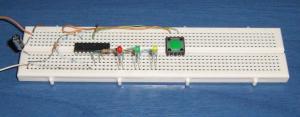
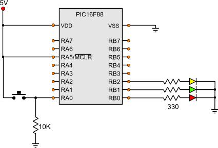
Each LED is lit from another subroutine. The RED LED will light on a single click, the GREEN on a long press and the yellow on a double click.
The Code
The code is a little bit complicated, as many parameters needs to be taken into account during a click. Also, some extra delays are added for avoiding false triggers (debounce technique).
; RAM preserved -----------------------------------------------------------
	cblock 0x20
		WaitCounter,WaitCounter2
		IntervalCounter
	endc
; Conastants --------------------------------------------------------------
GLDoubleClick_Interval	=	d'15'	;mSec x 10
GLDoubleClick_MaxDelay	=	d'30'	;mSec x 10
GLLongClick_Interval	=	d'80'	;mSec x 10
; Main Program ------------------------------------------------------------

Start
				bank1				;Go to bank 1
				movlw b'11111111'		;
				movwf TRISA			;Set the port pin types of the RA

				movlw b'11111000'		;
				movwf TRISB			;Set the port pin types of the RB
				bank0				;Go to bank 0

				bcf ClickOutput
				bcf DblClickOutput
				bcf LngClickOutput

MainLoop
				btfss ButtonInput
				goto MainLoop

				movlw GLLongClick_Interval
				movwf IntervalCounter
CheckForLongClick
				call Wait10mSec
				btfss ButtonInput		;Check if it is a long click
				goto NoLongClick
				decfsz IntervalCounter,f
				goto CheckForLongClick

				;It WAS a long click
				goto Run_Long_Click

NoLongClick							;It was NOT a long click
				movf  IntervalCounter,w
				sublw GLLongClick_Interval	;Check How many mSeconds was the first keypress

				sublw GLDoubleClick_MaxDelay	;Was it MORE thant the max dbl initial click?
				btfss Carry			;If the result is negative
				goto Run_Single_Click		;Then it was a single click.

				;Else, we will wait more to see if it will be a dbl click
				movlw GLDoubleClick_Interval
				movwf IntervalCounter

CheckForDblgClick
				call Wait10mSec
				btfsc ButtonInput
				goto It_Is_A_Dbl_Click

				decfsz IntervalCounter,f
				goto CheckForDblgClick

				;It WAS a Single click
				goto Run_Single_Click

It_Is_A_Dbl_Click
				call Wait2mSec
				btfsc ButtonInput
				goto It_Is_A_Dbl_Click		;Wait untill the button is released
				goto Run_Dbl_Click

Run_Single_Click
				bsf ClickOutput
				call Wait1Sec
				bcf ClickOutput
				goto WaitForKeyReleaseBeforeReturn
Run_Dbl_Click
				bsf DblClickOutput
				call Wait1Sec
				bcf DblClickOutput
				goto WaitForKeyReleaseBeforeReturn

Run_Long_Click
				bsf LngClickOutput
				call Wait1Sec
				bcf LngClickOutput
;				goto WaitForKeyReleaseBeforeReturn	;This instrruction is not really nesecary here!

WaitForKeyReleaseBeforeReturn
				call Wait4mSec
				btfsc ButtonInput
				goto WaitForKeyReleaseBeforeReturn
				call Wait10mSec
				goto MainLoop
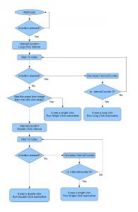
We start by defining the pin types. Right after, we clear the three outputs so that the LEDs are turned off. The MainLoop this time is... 2 instructions long! It checks if the button is pressed. If not, it loops back to MainLoop. If it is, it will continue with the click type check. Trying to describe this subroutine with words would complicate the things even further. Therefore, i have add the following flow chart that describes only this subroutine:
So, after this subroutine, one of the three click-subroutines shall run. It will be either a single, a double or a long click. According to the subroutine call, the corresponding LED shall lit. Also, the LED shall remain ON for one second and then it will turn off again. Then, the program flow shall return back to MainLoop. But before this is done, we need to ensure that the button is not still pressed (for example after a double click that the second click could be still active). Therefore, i have add another small subroutine that is called after every click/dbl click/lng click subroutine execution. This subroutine will check every 4mSec the state of the button. If the button is not pressed, then it will wait another 10mSec (for debouncing) and it will go back to MainLoop.
iam sorry but could you help me
i want to turn on a led by pressing on a switch and wont turn off till a minute is passed or the by pressing on the same switch
At 12 November 2014, 1:26:43 user john wrote: [reply @ john]
hey really cool circuit thanjs for shearing :) so i have search for really long for a circuit really like this only that each click the light stays on well what i woul really like is that the firts click switches on 2 leds 3.5 20mh each & the second click the first leds of and the second 2 on same 3.5 20mh each & then click number 3 is again off :) thats it :) if you can help it would be super Thanks & Best Regards.
At 7 January 2014, 9:44:23 user Adam wrote: [reply @ Adam]
Hi,
I'm not sure I understand timing correctly. Long click should be 800ms (80x10ms), but I thought single repeat of those lines:
1. CheckForLongClick
2. call Wait10mSec
3. btfss ButtonInput
4. goto NoLongClick
5. decfsz IntervalCounter,f
6. goto CheckForLongClick
would add to 13ms, as lines 2, 3, 5 and 6 are executed repeatedly until 0 is reached in the register. Wouldn't the lines 3,5,6 add an extra 1ms each to the count, giving in total 80x13ms = 1040ms?
Could you explain it in more detail, please.
Very nice keypress routine! I also like simple user interfaces and rotary encoders are great for that. I was able to implement your code into my rotary encoder routines so now I have 5 functions from using 3 PIC ports. Rotary Left, Rotary Right, Single Press, Double Press, and Long Press for the rotary push button switch. I only changed the long key press from 800ms to 1500ms because I use it for a SET-UP menu and don't want to display it unless the key is held down for awhile. Very Cool! Thanks!
Yes there are problems with relays near PICs, not because of the relay itself (you need to have a protective diode and maybe a capacitor), but mainly due to the current of the contacts of the relay that sparks. If you plan to have AC, then most probably you need an inductor. Look this circuit:
K1 controls an AC load. Without the inductor (L1), the PIC resents most of th times that the relay makes or breaks contact.
I have never test the udn2981, but i suppose it would work. I prefer transistors.
As for the distance, there will be no problem placing the relays a mile away, as long as the voltage of the coil and the current are enough. That has to do only with the transistor driver and not with the PIC itself
COOL STUFF!!
This project was what I was looking for in the internet. Thank U very much!
My question about modifying:
I want to drive 8 relays using a similar sourcecode but using all 8 outputs. I heared about problems with relays being next to the pic.
Should I use a udn2981 as relay-driver?
Should I place the relays away from the pic or is this incorrect?
Hi rashid,
You need to have all the files in the same directory. This is important! As for the MPLAB, although you do not need to put the inc files in the MPLAB, it is recommended for your ease. I suggest you start the PIC book from the beginning where i explain how to put files in the MPLAB:
http://pcbheaven.com/picpages/MPLAB-Environment/
clever button project
i downloaded the zip files but i do not know how to link them into mplab.i attached the .asm in the project under sourche folder. for the other 3 .inc files don\'t know where to put them. can you please show me how
I am sorry i am not familiar with this editor. What is this mci file? In the zip i have 4 files, one ASM and 3 INC. You can simply find the lines that i include each INC file inside the assembly ( you search for something like "include init_normal.inc") and delete this line. At this position, you copy/paste the contents of the appropriate file. # inc files means that you search for 3 different "include" commands.
thanks for clarification.
but i am using picbasic as my editor
do i take these 3 files in your zip file and merge into one ?
but then i cannot seem to open file "cleverbutton.mci"
please help
Please make sure that you have download the complete project and NOT just the code provided in the code box. This is only for explanation. There are some constants that are declared in other files. ALL files are inside the zip file. Download the zip from the section "The project Files". Just click on the link "PIC Tutorial - A Clever Button" that you will find (it is right above these comments! ^^^^^)
That would be simpler. Do as shown in sub "CheckForLongClick", but put two control lines like this one "btfss ButtonInput || goto NoLongClick". The first one will check for the button No1, and the other for button No. 2.
This is excellent very well done, how about if you had two buttons and wanted differing outputs, if say two buttons pressed simultainiously for 1 sec, perhaps in order to the duration that the LED's stay's lit.
Shaun
No part of this publication may be reproduced, stored in a retrieval system or transmitted in any form or by any means, electronic, mechanical, photocopying, recording, scanning or otherwise without the prior written permission of the author.

 Home
Home
 Projects
 Experiments
 Circuits
 Theory
 BLOG
BLOG
 PIC Tutorials
 Time for Science


 Contact
 Forum
Forum
 RSS
RSS

 Click type check flow chart