
|
 Home Home
 Projects Projects
 Experiments Experiments
 Circuits Circuits
 Theory Theory
 BLOG BLOG
 PIC Tutorials PIC Tutorials
 Time for Science Time for Science
|
| ||
|
6 March 2009 Author: Giorgos Lazaridis Interfacing ICsThe problem of interfacing ICs It is commonly known that IC, even if those belong in the same family, do not always interface themselves with a single wire. There come times that ICs from different families of with different power supply, needs t be interfaced somehow. TTL for example are powered with 5V and CMOS can be powered with 3 to 15 Volts. Also, the high and low states of TTL and CMOS are not the same. Another common example is when one output of an IC needs to be interface with multiple inputs of other ICs. In such (and many more cases), to ensure proper and stable operation, interfacing methods should be taken into consideration. Find bellow the most common (and hard working) methods to interface ICs together, ICs that may belong to different families with same or different power source/voltage. Interfacing ICs under 5Volts power supply Interfacing a CMOS to a TTL under 5Volts power supply
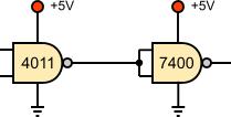
The high state of the CMOS output is enough to drive directly a TTL input into high state without problems. The low state could though could cause malfunctions in some cases. Is it possible to sink a TTL input current into low state without exceeding the maximum value of the TTL low state input voltage? Typical CMOS gates are specified to sink about 0.4 mA in the low state while maintaining an output voltage of 0.4 volts or less, sufficient to drive two LS TTL inputs or one Schottky input (Fig. 1.a), but insufficient to drive standard TTL. In this case, a 4041 buffer (or another buffer) should be used to eliminate this problem (Fig. 1.b). Interfacing a TTL to a CMOS under 5Volts power supply  Fig. 2
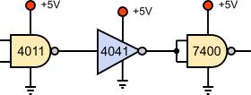
Interfacing ICs with different power supply voltages Interfacing a CMOS to a TTL with different power supply voltages 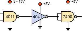 Fig. 3
Interfacing CMOS to TTL with different voltages is as easy as with same voltages. The reason is because the CMOS can be supplied also with 5V like the TTL. So, a 4041 buffer can be powered with 5V to do the interface. In the following drawing, the 4041 could be omitted if the 4011 was supplied with 5V. Interfacing a TTL to a CMOS with different power supply voltages
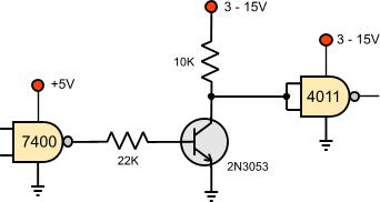
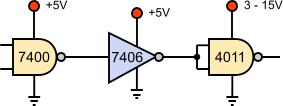
In this case, a use of NPN transistor a essential to implement the interface (Fig. 4.a). The base of the transistor is controlled by the output of the TTL chip. When it is in low state, the collector voltage is nearly the CMOS voltage. When the TTL output is driven into high state, the transistor is driven into saturation causing the CMOS input to become nearly 0. This interface is also causing an inversion of the signal so be sure that you have this in mind during designing. Another technique is the use of an open collector TTL buffer like 7406 (Fig. 4.b). This technique is useful if you have multiple outputs to interface. The 7406 VDD pins are connected to the TTL's power line (5V). Relative pages Comments
|
|
 Contact Contact
 Forum
Projects
Experiments
Circuits
Theory
BLOG
PIC Tutorials
Time for Science Forum
Projects
Experiments
Circuits
Theory
BLOG
PIC Tutorials
Time for Science
 RSS RSS
Site design: Giorgos Lazaridis © Copyright 2008 Please read the Terms of services and the Privacy policy |


 Reddit this

