|
11 March 2009 Author: Giorgos Lazaridis Dimmer Theory
What is a dimmer?
A dimmer is a device that is originally created to control the brightness of lamps. This is done by altering the total power delivered to the lamp and thus the brightness. The following schematic demonstrates a basic type of dimmer:
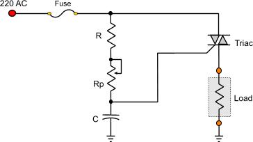
The resistor R is a protective resistor for the triac's gate. The potentiometer Rp along with the capacitor C, controls the time that the triac will be conductive, counting from the zero point of the input waveform.
Operation principles
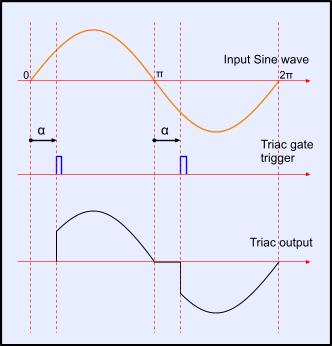
The operation of the dimmer is based on the fact that, during a full cycle of an AC waveform, a thyristor will only allow a part of the waveform to be delivered to the load (lamp). Take a look at the following waveforms:
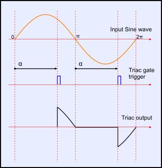
Both waveforms above comes from the same dimmer. The only difference is that the waveform on the left will bright the lamp higher than the waveform on the right. That is because, on the left waveform, the triac will be conductive earlier than the triac shown in the right waveform.
The time that the triac becomes conductive is symbolized with the Greek letter α (ALPHA) and is measured in angles from the zero point of the waveform. This zero point is the point that the voltage is 0 volts, and this happens 2 times every one full period of the wave form. When the α becomes smaller, then the dimmer becomes conductive sooner and the lamp is brighter. When the α becomes bigger, then the triac delays more to become conductive and thus the lamb is dimmer.
A full wavelength period is 360 degrees (2π). Due to the fact that during a full wave length the zero cross occurs twice, α can take values from 0° to 180 degrees (0 - π). When α = 0°, the full power is delivered to the load and when α = π, no power is delivered to the load.
Zero cross detection
 A basic dimmer using a microcontroller A basic dimmer using a microcontrollerThe zero cross detection circuit is the most critical part when designing a dimmer. This circuit will watch the input power waveform and detect when this waveform crosses the 0 point and becomes 0 volts.
Zero cross detection circuits are mainly used in cases when the dimmers needs to be controlled from a micro controller. In that case, the micro-controller needs to know the zero cross detection point of the waveform, so that it can calculate the angle offset to send the trigger pulse to the gate of the triac.
Here is an example calculation. Suppose that the AC power oscillates in a 50Hz cycle. This means that each cycle will take 1/50Hz = 20 mSec to be completed. During those 20mSec, the waveform will cross the zero point two times, one at the beginning and one in the middle of the cycle, that will be after 20/2 = 10mSec.
If we want the lamp to be half the way bright, then the microcontroller needs to send a pulse in the middle of each semi-cycle. Thus, a pulse must be sent after 5mSec after each time the waveform passes the zero point. For this to be done, the microcontroller will watch the zero cross detection circuit (ZCD) for a pulse. When the ZCD send this pulse, the micro controller will count 5 mSec and then will trigger the gate of the triac.
The following circuit will perform a Zero Cross Detection circuit. This circuit is very stable and accurate, and has a controllable pulse width. Another great advantage is that because of the transformer, this circuit has a complete galvanic isolation with the mains supply so that it makes it completely safe and risk free of destroying the microcontroller due to power peaks.

DC dimmer
 A typical DC light dimmer / DC motor speed controller A typical DC light dimmer / DC motor speed controllerThe operating principle of a DC dimmer is completely different. When a triac becomes conductive, the only way to turn them back into a non-conductive state is to have 0 volts difference between it's pins. In the case of AC current, this happens twice every full period. But in the case of DC voltage, this would never happen and thus, when the dimmer become once conductive it will remain like that until the power is completely turned of from it's pins. This makes the triac inappropriate for DC power. Also, because DC power never crosses the zero point, the α parameter has no meaning to be used.
For those reasons, DC loads are controlled in a different way. The most popular and efficient way is the use of PWM switching signal to control the power delivered. A PWM signal between 1.5KHz and and 3KHz is applied to the base of a transistor. The transistor is used to drive the load. By altering the duty cycle of the PWM signal, we can change the brightness of the lamp. The higher the duty cycle, the brighter it lights and vice-verse.
Relative pages
The SCR (Silicon Control Rectifiers) theoryThe TRIAC theoryThe voltage divider theoryLearn how to interface ICs
Comments
At 4 January 2015, 14:50:25 user eded wrote: [reply @ eded]@Marc
I know it has been a while but I agree with what you say about about the transformer: it creates a delayed zerocross signal. I use an optocoupler to directly check the primary AC signal for my dimmer: http://www.instructables.com/id/Arduino-controlled-light-dimmer-The-circuit/
At 30 September 2014, 17:51:52 user Ronald wrote: [reply @ Ronald]Mr. Giorgos,
I agree with "Mr Triac" - the Load (the Lamp) should not be connected between Triac and Ground/Earth. That lead of the Triac should connect directly to Ground (Earth), the Load (Lamp) should be directly at the Line (Mains) input, with the Fuse directly after it, then connected to the Triac.
The same rule should be applied to your drawing for the microcontroller dimmer - the Load must be directly connected to the AC Mains input, then a fuse in series, then to the Triac which is the "switched" connection to Ground/Earth.
Also, a DIAC trigger diode must be used when triggered by an AC signal, as in your first circuit. This gives a predictable trigger point, well above zero volts. The only exception is if the Triac has an internal Diac on the Gate lead.
Remember, the goal is to trigger the Triac Gate voltage relative to the Grounded (lowest voltage) lead. If an illuminated Lamp is in series with that Grounded lead, then the Voltage of that lead of the Triac is now ABOVE Ground, so that the Gate trigger point is constantly moving - your Trigger Voltage will be required to move higher and it will not function properly.
The uController should never directly drive a Triac (even thorough a resistor), there must be galvanic isolation - always use an opto-coupler.
At 25 June 2014, 17:52:10 user khan wrote: [reply @ khan]my fan dimmer does regulate properly when power is supplied by local made ups ( square wave type of supply)
profkn7@gmail.com
At 2 February 2014, 9:29:08 user Giorgos Lazaridis wrote: [reply @ Giorgos Lazaridis]@Mrunal Ahirrao if you mean the duration of the gate pulse typically it is close or less to 1mSec. You need to consult the TRIAC datasheet for the details
At 24 January 2014, 13:41:09 user Mrunal Ahirrao wrote: [reply @ Mrunal Ahirrao]after the alpha how long should be the triac gate pulse should be on? to deliver the power as seen in waveforms.
At 3 December 2011, 21:44:31 user Mr Triac wrote: [reply @ Mr Triac]WARNING! This diagram of the basic type of dimmer(top of the page)is almost dysfunctional. The load must be tied in series with the FUSE not as shown in this figure. And the most important, the DIAC is missing.
At 30 November 2011, 16:03:32 user Kammenos wrote: [reply @ Kammenos]@rahultripathi the light is AC or DC? this dimmer is for AC. For more info, post schematics in the forum.
At 30 November 2011, 14:15:41 user rahultripathi wrote: [reply @ rahultripathi]i had use light dimmer using solid state relay but i am unable to get the smooth dimming effect
it will blink with certain interval
I had created pwm duty cycle with maximum 10 ms ,20ms delay
so plz.... give me the exact duty cycle to operate
and the way to calculate it
At 30 November 2011, 14:03:39 user rahultripathi wrote: [reply @ rahultripathi]actually i am trying to create pwm with 8051 along with solid state relay
but I can only dim the light with blinking effect
The output was nat smooth dim light
what is the total time period of duty cycle to operate
plz help
I had tried total time 10ms, 20 ms
even 5ms in this case it start dimming but with blinking effect
At 29 August 2011, 22:53:23 user Charlie X-Ray wrote: [reply @ Charlie X-Ray]Once again, nice article.
In the part you explain the zero cross detection you left a "50ms" that I think should be 5ms now.
Also a full wavelength is 2pi radians as you say but that is 360 degrees, not 180 and the same for pi radians that is 180 degrees, not 90.
See you.
At 16 August 2011, 19:03:00 user Kammenos wrote: [reply @ Kammenos]@Marc certainly there is (not as big as you may think though), but it would be noticeable only when you need the FULL waveform for full brightness. But when you do, then you simply have permanent the TRIAC turned on, so no worries.
Regarding the optocoupler solution you give, it is a very nice and clean solution that i may use in future project, where space is critical. The solution with the transformer where given when i had little experience with optocouples and their capabilities. Yet again, if space is not that critical, then i would never reject my transformer, because of the 100% galvanic isolation it provides. After all, you will need some sort of DC supply, won't you?
At 15 August 2011, 1:17:25 user Marc wrote: [reply @ Marc]Isn't there a "big" delay of the signal from the "pure" AC and the AC signal after the transformer?
Wouldn't it be more precise if we use, for example, the full-rectified AC signal (from the "pure" AC), feed it through an (for example) 4n25 and use a Schmitt trigger?
At 8 April 2011, 10:37:54 user kaypee wrote: [reply @ kaypee]Kammenos , I have used the first circuit shown in this page which operates on 220v ac. For making it automatic I used an LDR in series with potentiometer.But what is happening is that when light is falling on LDR the bulb is getting brighten, i.e. reverse function is occuring.How can I make it dim when light falls on LDR?
At 27 July 2010, 13:09:18 user Kammenos wrote: [reply @ Kammenos]Yes i have correct it already. Thanks for noticing
At 27 July 2010, 7:21:18 user RONY CHAKRABORTY wrote: [reply @ RONY CHAKRABORTY]YES That\'s true. 20ms for 50Hz and, 10 ms for Every Zero crossing Detection. Actually i made the circuit with Opto coupler. And working fine.
At 27 July 2010, 1:21:55 user Charlie X-Ray wrote: [reply @ Charlie X-Ray]Nice article.
The 50Hz signal period is 20ms not 200ms.
At 6 June 2010, 9:11:30 user RONY CHAKRABORTY wrote: [reply @ RONY CHAKRABORTY]Nice Article. I was building an Dc/Ac inverter where charging part is designed with Triac. the theory of ac dimmer was the important to study. and this article helped me to design perfectly. thanks thanks ... |
|
 HOT in heaven! HOT in heaven!

|
|

 Home
Home
 Projects
 Experiments
 Circuits
 Theory
 BLOG
BLOG
 PIC Tutorials
 Time for Science


 Contact
 Forum
Forum
 RSS
RSS


 Reddit this
