|
 Home Home
 Projects Projects
 Experiments Experiments
 Circuits Circuits
 Theory Theory
 BLOG BLOG
 PIC Tutorials PIC Tutorials
 Time for Science Time for Science
|
| ||
|
PIC Tutorial - A 3-digits Decimal Counter
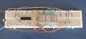 This tutorial uses exactly the same circuit as the previous one, as well as the technique to interface three displays with using only 11 pins from the PIC. Therefore, you should read first the previous tutorial to be familiar with this technique as it will be not discussed here. This tutorial will demonstrate a binary counter. It will count from 000 to 255. The number 255 is the max decimal value for an 8-bit byte. It could be of course extended to any length, but because we are still at the beginner's section it will be kept as easy as possible. In Action The Circuit The circuit is the same as the previous tutorial: 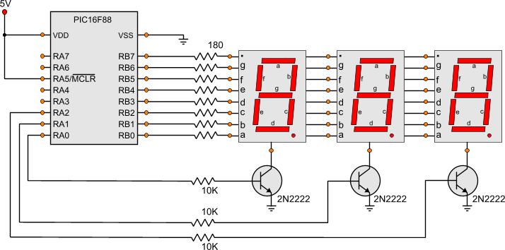
For detailed informations on this circuit, look at the previous tutorial The Code Here is the code for this tutorial: ; RAM preserved ----------------------------------------------------------- cblock 0x20 WaitCounter,WaitCounter2 Counter Huns,Tens,Ones PassArg1,PassArg2,PassArg3 DelayCounter endc ; Main Program ------------------------------------------------------------ Start bank1 ;Go to bank 1 movlw b'11111000' ; movwf TRISA ;Set the port pin types of the RA movlw b'00000000' ; movwf TRISB ;Set the port pin types of the RB bank0 ;Go to bank 0 clrf Counter bcf Left_Seg bcf Mid_Seg bcf Right_Seg MainLoop movf Counter,w movwf PassArg1 call Bin8ToDecimal movf Huns,w movwf PassArg1 call BinaryTo7_Seg movwf Huns movf Tens,w movwf PassArg1 call BinaryTo7_Seg movwf Tens movf Ones,w movwf PassArg1 call BinaryTo7_Seg movwf Ones movlw d'10' movwf DelayCounter ShowNumbers bcf Left_Seg movf Ones,w movwf Segments bsf Right_Seg call Wait4mSec bcf Right_Seg movf Tens,w movwf Segments bsf Mid_Seg call Wait4mSec bcf Mid_Seg movf Huns,w movwf Segments bsf Left_Seg call Wait4mSec decfsz DelayCounter,f goto ShowNumbers incf Counter,f goto MainLoop BinaryTo7_Seg movlw b'00111111' ;Number 0 movf PassArg1,f btfsc zero return movlw b'00000110' ;Number 1 decf PassArg1,f btfsc zero return movlw b'01011011' ;Number 2 decf PassArg1,f btfsc zero return movlw b'01001111' ;Number 3 decf PassArg1,f btfsc zero return movlw b'01100110' ;Number 4 decf PassArg1,f btfsc zero return movlw b'01101101' ;Number 5 decf PassArg1,f btfsc zero return movlw b'01111101' ;Number 6 decf PassArg1,f btfsc zero return movlw b'00000111' ;Number 7 decf PassArg1,f btfsc zero return movlw b'01111111' ;Number 8 decf PassArg1,f btfsc zero return movlw b'01101111' ;Number 9 return The code has grown larger. The idea is still simple. A counter ('Counter') is increased on every cycle loop. The counter carries a binary number from 0 to 255. Then, the value of the Counter is loaded every time to a temporary register named 'PassArg1'. The subroutine 'Bin8ToDecimal' is then called. This subroutine is located inside the header file 'bcdToDecimal_3Digits.inc' that is included in the project. When this subroutine is called, it will convert the binary number in 'PassArg1' into three decimal digits. Those digits will be at the 'Huns', 'Tens' and 'Ones' registers. We still need a way to convert them into the corresponding binary numbers to be visualized on the 7-segs. This is done by calling the subroutine 'BinaryTo7_Seg'. Immediately after the binary to decimal conversion, the 'Huns' register is loaded to the temporary 'PassArg1' register, and the 'BinaryTo7_Seg' subroutine is called. The first thing done in this subroutine is to load the number for the '0' digit to the W register. Then it will check if the 'PassArg1' was zero and if it was, it will return back. If not, it will load the number for the digit '1'. The 'PassArg1' will be decreased ones and if it becomes zero it will return back. Then it will load the digit '2', decrease once more the 'PassArg1' and if it then becomes zero it will return back. This is done up to the digit '9'. So, according to the number that exists in the 'PassArg1' register, the W register will have the corresponding binary number that will be visualized on the display. When the program flow returns from the 'BinaryTo7_Seg' subroutine, the W register will have the binary number that corresponds to the number in the 'Huns' register. this binary number is immediately stored back to the 'Huns' register for later use. The same procedure is done for the 'Tens' and the 'Ones' registers. Remember that those 3 registers carries the three digits for the decimal number of the Counter. Each register carries a number from '0' to '9'. When all digits have been converted from decimal to 7-seg digits, it's time for visualization. The procedure is detailed explained at the previous tutorial. The same procedure is done here in the 'ShowNumbers' subroutine. You should notice that above and bellow this subroutine, the following code exists: movlw d'10' movwf DelayCounter ShowNumbers . . . . decfsz DelayCounter,f goto ShowNumbers This code will now create the delay between the number changing. It would be easier to call out well-known delay subroutine to make a 250mSec delay for example. But in that case, for 250mSec the displays would be all turned off. So this is not the correct way. Instead, we will use the same subroutine that displays the numbers to create the delay. We load the number '10' to the 'DelayCounter' register. Then we run the subroutine that displays the numbers. At the end, we decrease once the 'DelayCounter' register. If it becomes zero, the program flow continues normally and it will loop back to the beginning. But if it is still not zero, it will display the numbers once more. This will happen for 10 times. The delay between each number change is approximately 110mSec. As you understand, the time calculation is a big headache when dealing with simultaneous procedures. Here for example, we want to have digit display and time counting at the same time. There will be situations that more than 3 procedures will have to run at the same time. For example, the display, the time keeping, the button watching and an alarm will need to run at the same time if you make a clock! During the Advanced lessons, the time calculation will be explained in details. The project Files Following are the files for this project:
Comments
No part of this publication may be reproduced, stored in a retrieval system or transmitted in any form or by any means, electronic, mechanical, photocopying, recording, scanning or otherwise without the prior written permission of the author. Read the Disclaimer
All trademarks used are properties of their respective owners.
Copyright © 2007-2009 Lazaridis Giorgos. All rights reserved. |
  
|
 Contact Contact
 Forum
Projects
Experiments
Circuits
Theory
BLOG
PIC Tutorials
Time for Science Forum
Projects
Experiments
Circuits
Theory
BLOG
PIC Tutorials
Time for Science
 RSS RSS
Site design: Giorgos Lazaridis © Copyright 2008 Please read the Terms of services and the Privacy policy |

 PIC Tutorial - A 3-digits Decimal Counter