|
 Home Home
 Projects Projects
 Experiments Experiments
 Circuits Circuits
 Theory Theory
 BLOG BLOG
 PIC Tutorials PIC Tutorials
 Time for Science Time for Science
|
| ||
|
PIC Tutorial - Interface Multiple 7seg Digits
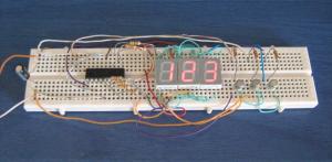 The circuit on a breadboard. Things are getting a little bit more complicated here. We want to have three different 7-seg that each one will show a different number. Normally, we would need 7 pins for each one, so a total of 21 pins are required, right? No, because in that way, if we wanted to have 6 digits (for a frequency meter for example) we would need 42 pins! Instead, we will make a trick, a trick with the eye. The catch is that the human eye does not operate non-stop all the time. Instead, it takes 10 'photos' each second. Between those photos, the brain will keep the last photo taken active, something like a 'latch'. We will take advantage of this characteristic for this circuit. In Action The circuit here is the circuit of this tutorial: 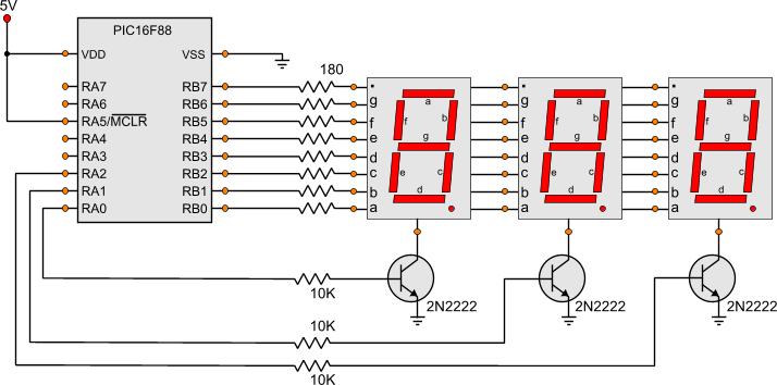
As you can see, we only use the 8 lines from PORTB for the segments (7 segments + one for the dot) and three more lines, RA0, RA1 and RA2 for the drive-lines for the displays. All digit segments are connected in parallel using only one set of limiting resistors. The common-cathode pin of each display is not connected directly to ground. Instead, a 2N2222 transistor is connected between and used as a switching transistor. Only one display is active at a time and it remains active for about 4mSec. Then this display is turned off and the next one is active for 4mSec. Because the displays are turned on and off very quickly, the eye will be tricked. The numbers will appear as if they are illuminated all the time. With this way, you can easily have many 7-seg displays connected using the 7 (or 8) pins for the segments and one extra pin for each additional display. The turn-on time that i have chosen is 4 mSec but you may need to reduce this time in case of more digits. Do not make it too small though. You can use a lower-value limiting resistor for the segments as long as the current does not excess 25mA. The Code Here is the code for lighting the displays: ; Definitions ------------------------------------------------------------- #define Left_Seg porta,0 #define Mid_Seg porta,1 #define Right_Seg porta,2 #define Segments portb ; Main Program ------------------------------------------------------------ Start bank1 ;Go to bank 1 movlw b'11111000' ; movwf TRISA ;Set the port pin types of the RA movlw b'00000000' ; movwf TRISB ;Set the port pin types of the RB bank0 ;Go to bank 0 MainLoop call HideAllSegments movlw b'00000110' ;Number 1 movwf Segments call ShowLeftSegment call HideAllSegments movlw b'01011011' ;Number 2 movwf PORTB call ShowMiddleSegment call HideAllSegments movlw b'01001111' ;Number 3 movwf PORTB call ShowRightSegment goto MainLoop HideAllSegments bcf Left_Seg bcf Mid_Seg bcf Right_Seg return ShowLeftSegment bsf Left_Seg call Wait4mSec return ShowMiddleSegment bsf Mid_Seg call Wait4mSec return ShowRightSegment bsf Right_Seg call Wait4mSec return First, we set all RB pins as outputs and the RA0, RA1 and RA2 as well. Then, the subroutine 'HideAllSegments' is executed. As you may have already notice, i love working with subroutines. Assembly is a low level programming language. There are times that your code will be tens or hundred of lines. To avoid confusion you should use subroutines frequently. You should use them wisely. A well written, well commented and with a proper name subroutine is sometimes the difference that will make your program to work or not. Back to the code, the subroutine 'HideAllSegments' is executed. This subroutine will turn off the RA0,RA1 and RA2 outputs, and thus, all 7-segs shall be turned off. This step is very important prior every digit/number change, otherwise the displays will not have a clear nice digit displayed. Then, a binary number which corresponds to the segments to show the number '1' is loaded onto the digit. Remember that all segments are turned off. This means that even if the number is loaded, nothing shall be displayed. Right next, the subroutine 'ShowLeftSegment' is executed. This subroutine shall turn on the left segment and the number will appear to it! A 4mSec delay is mandatory for the LEDs to achieve their full brightness and for the eye to take the 'photo'. Then, the displays are turned off again, the next number is loaded ('2'), the middle display is turned and kept that way for 4mSec. Finally, the same procedure with number '3' is done for the right (3rd) display. When all numbers are shown, the whole loop starts again from the beginning. The project Files Following are the files for this project:
Comments
No part of this publication may be reproduced, stored in a retrieval system or transmitted in any form or by any means, electronic, mechanical, photocopying, recording, scanning or otherwise without the prior written permission of the author. Read the Disclaimer
All trademarks used are properties of their respective owners.
Copyright © 2007-2009 Lazaridis Giorgos. All rights reserved. |
  
|
 Contact Contact
 Forum
Projects
Experiments
Circuits
Theory
BLOG
PIC Tutorials
Time for Science Forum
Projects
Experiments
Circuits
Theory
BLOG
PIC Tutorials
Time for Science
 RSS RSS
Site design: Giorgos Lazaridis © Copyright 2008 Please read the Terms of services and the Privacy policy |

 PIC Tutorial - Interface Multiple 7seg Digits