
|
 Home Home
 Projects Projects
 Experiments Experiments
 Circuits Circuits
 Theory Theory
 BLOG BLOG
 PIC Tutorials PIC Tutorials
 Time for Science Time for Science
|
| ||
|
9 April 2009 Author: Giorgos Lazaridis The ResistorHistory The Resistance was discovered by the year 1827 from Georg Simon Ohm, a German electrician. Ohm was born in Germany, in the city of Erlangen at 1787 and died at 1854. Georg Simon Ohm noticed that different materials that are considered as electrically conductive, will not allow the current to flow within their body with the same ease. The difficulty that each material had, had to do with some parameters such as the type of the material and some external factors such as the temperature or the humidity of the atmosphere. G.S.Ohm described this behavior and gave the name "Resistance". He then announced the Ohm's law that connects the resistance with the voltage and the current af follows:
The resistor is measured with Ohms as a memorial to it's inventor. Electrical resistance A material having 1 Ohm resistance, will allow 1 ampere of current to flow within this material, when a voltage difference of 1 Volt is applied to it's terminals. As defined by the International Electrical Congress in 1893, and by United States Statute, it is a resistance substantially equal to 109 units of resistance of the C. G. S. system of electro-magnetic units, and is represented by the resistance offered to an unvarying electric current by a column of mercury at the temperature of melting ice 14.4521 grams in mass, of a constant cross-sectional area, and of the length of 106.3 centimeters. As thus defined it is called the international ohm. What is a resistor As far as the electrical part is concerned, resistor is a very simple but basic electronic component designed to do exactly what the Ohms law is about, produce a voltage drop between its terminals (commonly just two). Resistors are used as parts in electronic circuits. They are extremely commonplace in most electronic designs and circuits. Resistors can be made of various compounds and films, as well as wire as you can imagine there are many categories of resistors in the market depending on your needs such as Carbon film resistors, Metal film resistors, Variable resistors (potentiometer), Power resistors, Wire wound resistors etc. When you want to use resistors in a circuit you need to know the primary characteristics which are their resistance (Ohms) and the power (Watt) they can dissipate. The electrical symbols of different kind of resistors are shown bellow: 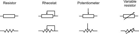
Resistor marking There are many different systems for resistor marking (basically depending on the type). the simplest way is the direct value indication system. This system can be easily applied to large-wattage resistors, as they may have larger housing. According to this system, the value is written as follows: 330 = 330 Ohms 3.3 = 3.3 Ohms 3K3 = 3.3 KOhms 3K = 3 KOhms As you can see, a K replaces the comma of the value in order to indicate that the value is in Kilo-Ohms. Otherwise, the value printed is in Ohms. If there is no decimal point in the value, then the 'K' is placed at the end of the number, for example 4K = 4KOhms. The most common system for small-housing resistor is the color code system. According to this system, the resistor is equiped with color bands. Each color represents a number and according to the position of the band, those numbers will perform the value of the resistor. Those bands could be 3, 4 or 5, according to the type, the material and the accuracy of the resistor. You will find more informations for this subject in our wiki-page "Reading parts value". You can also use our Metal Film Color Code Resistor Calculator and Carbon Film Resistor Color Code Calculator inside our Dr.Calculus pages. Do not miss also the Standard values calculator for the resistors! Relative pages Comments
|
|
 Contact Contact
 Forum
Projects
Experiments
Circuits
Theory
BLOG
PIC Tutorials
Time for Science Forum
Projects
Experiments
Circuits
Theory
BLOG
PIC Tutorials
Time for Science
 RSS RSS
Site design: Giorgos Lazaridis © Copyright 2008 Please read the Terms of services and the Privacy policy |


 Reddit this

