
|
 Home Home
 Projects Projects
 Experiments Experiments
 Circuits Circuits
 Theory Theory
 BLOG BLOG
 PIC Tutorials PIC Tutorials
 Time for Science Time for Science
|
| ||
|
21 March 2009 Author: Giorgos Lazaridis Reading Part ValuesWhat is a part value In electronics there are several different kind of parts, like resistors, capacitors, triacs, transistors etc. Each part family may have tens or hundreds or even thousands of part members, each one with different characteristics. To distinguish those characteristics, companies have create a code that is -almost- common for all part members of a family. This code could be a part number, like for example the 2N2222 transistor. In this case, the code is not descriptive but is used as an index. Thus, for someone to know the special characteristics of this part, should have the appropriate manual. In some parts that the characteristics are the same but only the value is changed, the code is descriptive. For the resistors family for example, we all know the characteristics of a resistor, we only need to know the value of the part. The code printed on the resistor indicates this very value. Because the non-descriptive codes are like a page number within a book with parts, this article will only explain and demonstrate how to read the descriptive codes. How to read part values Over the years, several coding methods have been used by manufacturers to describe the values of the parts. Some of them use letters, some numbers, some uses both letters and numbers and some use color code. The most common and most used methods are described bellow with detailed instructions how to read and decode them. Carbon film resistors color code The idea is simple. Hold the resistor with the tolerance strip on your right (D strip). This should be silver or gold (as a 20% tolerance is very rare). Then, read the first 2 strips beginning from the left side. Suppose that they are orange and yellow. This stands for 3 and 4 (orange=3 yellow=4) that is 34. The third strip is the multiplier. Multiply 34 by the multiplier color. If this color is red, the multiplier is 100. So, the resistance is 34*100=3400 ohm or 3,4 K. The tolerance is the last strip (first from the right). This shows the min and max value that this resistor may have. If the color for the above resistor is gold, then the min and max value should be 3230 (3400-5%) to 3570 (3400+5%) ohms. 

Metal film resistors color code Reading a value from a metal film resistor is the same as reading a value from a carbon film resistor, as described right above. The difference is that there are 3 significant digits instead of 2 and there is a wider range of tolerances. The methodology is exactly the same. You should use the following table for calculating those resistors: 

Capacitors alphanumeric code There are some kinds of capacitors that the value is clearly written on them, especially on electrolytic capacitors, like 10μF that stands for 10 micro-Farads. For them, the value is straight-forward. There are some smaller types of capacitors with a coded 2 or 3 digits number on them. If there are 2 digits printed on them, then this is the exact value in pico-farads. For example, 32 means 32 Pico-Farads. For the 3 digits code, the first 2 digits are the significant digits (in pico-Farads) and the third is the multiplier. The multiplier digit is as follows:
A capacitor with code 322 means 32*100 pico-Farads = 3200 pF=3,2 nano-Farads. Sometimes, a tolerance letter is also added at the end of the code. These letter tolerances are as follows:
So a 103J is a 10,000 pF with +/-5% tolerance Capacitors color code Things may get a little more complicated in this section so make sure that reading a value from a carbon resistor is clear for you. This color code is mostly applied to ceramic capacitors, but could be also met to other types of capacitors too. It is not very popular, but is good to know how it works. And here is how it goes: Same as a resistor, a capacitor's color code is read in even way. Notice that on the left side as you see the cap there mast be an thicker strip or the strip must be at the edge of the capacitor. If you have a disc type capacitor then there is no problem of course. The first strip is the temperature coefficient. You can ignore this strip. The second and the third strip are the significant digits and the fourth strip is the multiplier (result in pico Farads). Use the same methodology as reading a resistor to get the value of the capacitor. For example: Second strip: Orange (3) Third strip: Red (2) Fourth strip (Multiplier): Orange (x 1.000) This capacitor's value should be 32*1000=32.000 pF=32nF The tolerance is different for capacitors less than 10pF and for capacitors more than 10pF. For the previous example, the capacitor is more than 10pF. If the last strip was green, the tolerance should be +/-0.5%. Here is the color table for the capacitors color code: 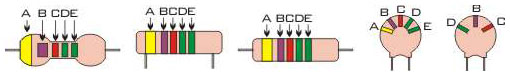 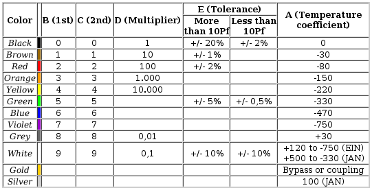
Mica and molded paper capacitors color codes There are 2 different code types that may be found on a mica capacitor, the 5 and the 6 digits code. In any case, an arrow is printed onto the face of the capacitor. While holding the capacitor, this arrow must be facing from left to right. Bellow there are three drawings. Drawing No1 and 2 shows a 5 digits mica capacitor. The arrow crosses the dots and is not solid. Drawing No3 shows a 6 digits capacitor. The arrow is solid. The top left dot shows if the capacitor is mica or molded paper. 
Because of those 5 and 6 digits code, you should use the appropriate color table from bellow accordingly. For the 5 digits color code use this color table: 
For the 6 digits color code use this color table: 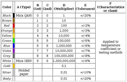
Tantalum electrolytic capacitors color codes Similar to the other capacitors, find bellow the Tantalum electrolytic capacitors color code. 

Is there an easier way? Or at lest a faster one? Reading part values is an easy part for a trained person. Someone needs only to learn the series of colors and practice a little bit and that's all. But thankfully there is an easier way for the beginner. There are thousands of calculators found around the internet. Following we present to you the ones created from the PCB Heaven staff. Please note that all calculators requires from you to have javascript enabled to operate.
Standard parts values Most of the times, when designing an electronic project, the calculated values for the part are usually not produced. A resistor 317Ohms for example cannot be found, therefore the designer has to search and find the closes resistor value near to his calculations. Here is the how-to for selecting the appropriate part values that can be found in the market. Resistor standard parts values The resistor standard values are categorized according their tolerance. There are the following categories: For each of the above categories, some tables shall be given with the base values. Those values can be multiplied by a multiple or division of 10 and the series of resistors shall be created. Look ate the following tables:
Suppose now that we need to find a resistor that according to our calculations needs to be about 338 Ohms. We select a tolerance of 5%, therefore we shall look to the E24 series. The closest to 338 is the 3.3 multiplied by 100. That gives us 330 Ohms, and that would be our resistor to use! Searching for parts is a job that on one hand it has to be done when designing a project, on the other hand everyone would like to put someone else to do this lousy job. Therefore, standard parts calculators are found all over the net to do this job in no time. Follow this link to find and use our free online standard resistor values calculator. For those that love mathematics, the algorithm to calculate almost every standard part value is as follows: Val = d x 10(i/N) Where: d = The decate multiplier that could be 1, 10, 100, 1K, 10K etc i = 0...n - 1 and N = tolerance selector as follows:
Relative pages Comments
|
|
 Contact Contact
 Forum
Projects
Experiments
Circuits
Theory
BLOG
PIC Tutorials
Time for Science Forum
Projects
Experiments
Circuits
Theory
BLOG
PIC Tutorials
Time for Science
 RSS RSS
Site design: Giorgos Lazaridis © Copyright 2008 Please read the Terms of services and the Privacy policy |


 Reddit this

