
|
 Home Home
 Projects Projects
 Experiments Experiments
 Circuits Circuits
 Theory Theory
 BLOG BLOG
 PIC Tutorials PIC Tutorials
 Time for Science Time for Science
|
| ||
|
22 March 2009 Author: Giorgos Lazaridis Connecting ResistorsConnecting resistors in series A series circuit is a circuit that all components are connected in series with one's end connected to the other's beginning. The following circuit shows three resistors connected in series: 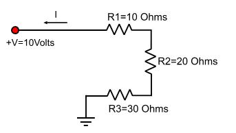
Total resistance in series connection The total resistance is the mathematical sum of all resistors and it is bigger than the part with the biggest resistance. In our previous example, the total RTOTAL is: RTOTAL = R1 + R2 + R3 = 10 + 15 + 25 = 50 Ohms, in general RTOTAL = R1 + R2 + ...+ Rn Current flow in series connection Current is the same for all parts in the circuit and it is equal to I total. Using the Ohm's law, you can calculate the total current: ITOTAL = V / RTOTAL This amount of current is equal for every part. This means that ITOTAL flows through R1, R2 and R3 and it is 10Volts / 50 Ohms = 0.2 Amperes = 200 mA Voltage drop in series connection The sum of the voltage drops on every part in a series circuit is equal to the applied voltage. Every part connected to a power supply causes a voltage drop that can be measured on it's pins. This voltage drop can be calculated by the ohm's law and it is: U = R x I. In a series circuit, every resistor may have different voltage drop measured on it's pins but adding all drops of every component must have the supply voltage. So: U1 = ITOTAL x R1 = 0.2 x 10 = 2 Volts U2 = ITOTAL x R2 = 0.2 x 15 = 3 Volts U3 = ITOTAL x R3 = 0.2 x 25 = 5 Volts U1 + U2 + U3 = 2 + 3 + 5 = 10 Volts. In general: V = U1 + U2 + ... + Un Connecting resistors in parallel A parallel circuit is a circuit that all components are connected in parallel, the beginnings and the ends of all components connected together. The following circuit shows three resistors connected in parallel: 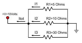
Total resistance in parallel connection The total resistance of the circuit is calculated with the following type and it is smaller than the part with the smaller resistance: 1/RTOTAL = (1/R1) + (1/R2) + ...+ (1/Rn) In our example: 1/RTOTAL = (1/R1) + (1/R2) + (1/R3) => 1/RTOTAL = 0.2 + 0.1 + 0.05 => 1/RTOTAL = 0.35 => RTOTAL = 2.857 Ohms An exception that makes our life easier is if we have to calculate only two resistors in parallel. In this case, there is a special type that can calculate the R total and it is: RTOTAL = (R1 x R2) / (R1 + R2) It looks more easier to calculate. If we have more than two resistors this type cannot be applied directly. It is possible to calculate the Rtotal in steps by calculating each time two resistors. In our example: Ra = (R1 x R2) / (R1 + R2) => Ra = 50 / 15 = 3.3333 and RTOTAL = (Ra x R3) / (Ra + R3) => RTOTAL = 66.6666 / 23.3333 = 2.857 Ohms. Some people do prefer this method as it is easier to calculate it 'by heart' without calculator. Current flow in parallel connection The total current drawn by the source is the mathematical addition of each current that flows through every part. ITOTAL = I1 + I2 + ... +In where Ixxx is the current that flows in every part of the circuit. In our example, this means that: I1 = V / R1 = 10 / 5 = 2 Amp I2 = V / R2 = 10 / 10 = 1 Amp I3 = V / R3 = 10 / 20 = 0.5 Amp Voltage drop in parallel connection Voltage drop is the same for every part in the circuit. Obviously, this is true as every part is connected directly to the power supply. This is very helpful to know when you have some parts like 12Volt lamps to connect to a 12Volt power supply. Connecting them in parallel will make sure that every lamp will have 12Volts on it's pins. Relative pages Comments
|
|
 Contact Contact
 Forum
Projects
Experiments
Circuits
Theory
BLOG
PIC Tutorials
Time for Science Forum
Projects
Experiments
Circuits
Theory
BLOG
PIC Tutorials
Time for Science
 RSS RSS
Site design: Giorgos Lazaridis © Copyright 2008 Please read the Terms of services and the Privacy policy |


 Reddit this

