Home     Contact     Projects     Experiments     Circuits     Theory     BLOG     PIC Tutorials     Time for Science     RSS     Terms of services     Privacy policy  
   
 Home      Projects     Experiments     Circuits     Theory     BLOG     PIC Tutorials     Time for Science   

26 January 2010
Author: Giorgos Lazaridis
PC System Health Monitor


Worklog - The results from the cabinet change (March 20 2010)

I let the system running non-stop for about a month or more. The following images are taken with many days difference between each other:


The system runs super-stable. The three HDDs are from 4 to 5 degrees above ambient temperature, ranging from 26 to 29 degrees. The 4th HDD is all the time 2 degrees above ambient temperature. No it has nothing to do with the location or the usage of the HDD, i test it myself. This HDD is a Western Digital -GREEN HDD. I can only say that... yes... the GREEN technology works!. 50% thermal load reduction!

The temperature difference between the inlet and the outlet is between 1 to 3 �C. Moreover, the North lane and South lane seems to have up to 1�C difference, which is something that i really did not expect. The PSU is no more a significant thermal load. After all, the air outlet of the PSU is directly before the outlet of the box. The heavier thermal load comas from the CPU. About 13 - 14 degrees above ambient. I did not measure temperatures above 36 degrees. Taking into account that my CPU is designed to operate in temperature ranges between 5 and 71.4 degrees, the 36 degrees is like my CPU is near the seaside drinking cocktails.

What i did notice though, is that i had many rpm ups and downs. Also, one of my inlet fans stalled once. That was a sign from above, telling me to "Change the rpm control method of the inlet fans". If you have read the article from the beginning, i run these fans with averaging a PWM frequency, rather than sending PWM pulses directly to the fans.

The circuit that i used for these fans is located here. I need to make some changes. First of all, i will remove the averaging capacitors C4 and C8. Maybe, i will completely remove the circuitry around the 741 and the 741 itself, and leave only the zener and R7. Then i will change the firmware of the PIC. I tried my best to find a method to control 3-wire fans and have also rpm feedback out of it. I will BLOG my experience and explain the various ways i tested. The final (i hope) firmware version will use pulse stretching.

BACK TO THE LAB!


... two days later (March 20 2010)

So, a couple of days later, i had everything ready. I uploaded the new firmware to the PICs. Also, i removed the 741 OP-AMPS from the circuit. Although they did not cause any problem, They did not help at anything. The pulse stretching method just works! The new circuit is according to this PWM 3-Wires Fan Controller with RPM feedback (Pulse Stretching Method).

I also removed the annoying capacitors that i used before for averaging the voltage. Now the fans are powered with pure PWM. The great thing is that from 800rpm (that i take as minimum) up to 1800rpm (the maximum of the fans), there are about 80 speed steps! Well, i do not think that this is a practical advantage, i mean 10 steps would be enough, but hey, better more than less.

I did not mount the circuit on a new PCB. Instead, i hacked my old PCB. I un-soldered the capacitors, removed the 741 from its bases and bridged the pin 2 with the pin 6 (reverse input and output pin) of the 741. The following photo indicates the hacked PCB: (the original PCB is located here)
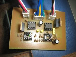


Now the same story again. I will let the system operate for a week or so. During this time, i will note and correct any flaws or bugs. I am not sure if i will make a new PCB - lighter than the existing one. If this one works, i will let it as-is. But from the very first hour of operation, i can see that the operation is dramatically improved. The input fans have almost the same rotation speed without asymmetries. The operation is smoother and the rpm change (whenever needed) is always successful - slower though, but this is not a problem after all.


Comments

  Name

  Email (shall not be published)

  Website

Notify me of new posts via email


Write your comments below:
BEFORE you post a comment:You are welcome to comment for corrections and suggestions on this page. But if you have questions please use the forum instead to post it. Thank you.


  • At 14 February 2010, 17:23:23 user Kammenos wrote:   [reply @ Kammenos]
    • I should have mention it in the article. I may add it later on. I add the cap because i could not drive with PWM this fan and get rpm feedback at low rpms. I have face the stall problem myself using other fans. But this fan has not any particular problem by reducing the voltage. After all, i will never drive them below 800rpms. And this circuit can go even lower w/o stalling the fan.
      Actually, the problem with PWM was that (maybe you have face it also) from lower to higher rpms, the duty cycle was changed only a couple of steps %. I tried from very low frequencies up to very high frequencies, still the regulation was terrible. That's the reason for this cap.


  • At 14 February 2010, 16:41:19 user Tom Hargrave wrote:   [reply @ Tom Hargrave]
    • I have not even had time to build your initial circuit - I\'m too busy supporting our original speed controller and designing a new temperature controller right now but will get to this soon. And when I do I\'ll send you the results.

      I see that you have added a 470uF cap across your FET, converting your PWM back to a noisy switching power supply. Can you explain why you added the cap?

      We tried a cap across our switching tansistor but found that the motor tended to stall at lower RPMs. But we did come up with a design using a smaller cap & second resistor in the power transisitor drive circuit that stretches the transistor on ramp and reduces the on-pulse kick from a loud growl to very soft pulses. This change would not work with your circuit because you are running at a much higher frequency than we are.


  • At 14 February 2010, 12:35:41 user Kammenos wrote:   [reply @ Kammenos]
    • Tom, i posted the new circuit. Will you test it with your fans? I look forward to hear the results.


  • At 13 February 2010, 14:37:54 user Tom Hargrave wrote:   [reply @ Tom Hargrave]
    • I realized after my last post that my logic behind sampling only when the fan is on flawed. With your higher frequency design, your RPM pulse train is slower than your drive frequency. To make this design work for you, you would need to convert the incoming RPM pulse into a shutter or gate then count the number of PWM pulses riding in on the pulse. And since the PWM frequency is a constant, you can translate the PWM pulse count into RPM.


  • At 13 February 2010, 7:40:56 user Kammenos wrote:   [reply @ Kammenos]
    • Yes, i changes the 4049 with an 741 that i have in stock. The reason for the 741, is that i have a lot of them to foll around. I will post the circuit or course.
      As for the second post, i suppose that this would work as well. This will dramatically reduce of course the signal reading interval(i read about once a second) because then it would be very hard to keep the rpm low.
      Will you try this? If you do, please post the results.


  • At 13 February 2010, 2:57:29 user Tom Hargrave wrote:   [reply @ Tom Hargrave]
    • I was sitting here looking at my O'Scope and eating my Dominos Pizza when the real solution just came to me!

      Instead of trying to condition the short pulses that occur when the fan is off, you should restrict your speed measurements to only when the fan is on. I'm assuming you can trigger a internal loop on the rising edge of the PWM on pulse? Then you can count incoming tach pulses across a fixed time window and calculate the fan's RPM from the pulse count. You may end up slowing your frequency back down in order to provide a wide enough window to measure your fan speed at all settings. You can even use a tach output pull-up resistor that's tied to your controller's 5V rail, possibly eliminating any need for signal conditioning.


  • At 13 February 2010, 1:33:32 user Tom Hargrave wrote:   [reply @ Tom Hargrave]
    • You don't state in the text but I assume you replace the circuit you built around the 4049N with your LM741 based trigger circuit? At least the components on your board supports this.

      It's been a long time since I designed anything around a LM741 OP Amp and the design is getting old. Maybe you can design the entire analog side around one LM324 OP Amp or if you want to stay with two 8 pin packages, something more efficient like a TLE2021?


    delicious
    digg
    reddit this Reddit this
    Faves


     HOT in heaven!


    NEW in heaven!


    New Theory: AC electric motor working principle


     Contact     Forum     Projects     Experiments     Circuits     Theory     BLOG     PIC Tutorials     Time for Science     RSS   

    Site design: Giorgos Lazaridis
    © Copyright 2008
    Please read the Terms of services and the Privacy policy