|
 Home Home
 Projects Projects
 Experiments Experiments
 Circuits Circuits
 Theory Theory
 BLOG BLOG
 PIC Tutorials PIC Tutorials
 Time for Science Time for Science
|
| ||
|
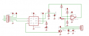
26 January 2010 Author: Giorgos Lazaridis PC System Health MonitorWorklog - New faster fans - new controller circuit (February 12 2010) In the meanwhile, i received a pair of 120mm Zalman fans for test. The only reason that i bought these fans is because they could rotate up to 1800rpm! Moreover, these fans draw 350mA, almost half a watt (0.42 Watts)! And at that speed, they sound like a helicopter... So, as you understand, i had to attach the rpm controller circuit (yeah, like i wouldn't). For my great disappointment, this circuit refused to co-operate with these two fans. More problems I use to say that the more the problems in a design, the more the pleasure when it works. But sometimes, this becomes ridiculously tiring. I used this circuit: PIC 3-Wire Fan RPM Controller Although i have test it with several fans from different brands, it seems that it can only co-operate with fans that rotate up to 1200rpm and not faster. The problem is the rpm feedback - of course. The signal from the feedback is rather noisy to drive it in the buffer. So, i used the good old Schmitt Trigger method. Hopefully, i do not have to further explain the ST, as i already have some pages for this: F.Y.I., i used a 741 Op-Amp to perform a single power supply Schmitt Trigger. I have make an on-line calculator for this kind of ST circuit that i used for my calculations: You can find more calculators for other kinds of ST circuits in the Dr.Calculus pages. Of course, i had a 3-days research to make them work properly. I used several different methods, different PWM frequencies (up to 90KHz!), different fan drivers, different filters. Only with the ST i managed to get a nice and smooth signal. So, except this, the rest of the circuit as well as the PIC program was exactly the same. The PWM frequency slightly differs. For these fans i preferred to use a frequency around 50KHz, as it gave me a better rpm response. At this point, i must admit that i am astonished by the performance of these fans. I managed to rotate them with a speed as low as 300rpm!!!!!! The feedback at this speed was still very clear and rectangular. And something more. It rotates with maximum speed (1750 rpm 10% tolerance) with just 10% duty cycle with no load (no filter-no pressure). Before this project ends, i will measure the pwer consumption of the fans, which i am sure it will be incredibly lower than the nominal power consumption. The new circuit Because of the 741 chip addition and the high frequency pulses, the PCB had to be bigger than the ones i made for the other fans. Thus, i decided to make one PCB for both fans. During the research, i made actually two PCBs. The first one rests in peace in the local junk-yard. The high frequency pulses increased the difficulty dramatically. It almost drive me crazy. Imagine this: One PCB carries two completely identical circuits, one for the left fan and one for the right. They have exactly the same parts. The left circuit works perfectly. The right circuit refuses to work correct. It runs for about 1 minute and then the PIC program flow collapses. There is NO obvious cut or line break on the PCB. After many hours over the PCB with a magnifying lens and a bucket of Greek instant coffee, i found one single line that carried the PWM pulses and was going through some pins of the PIC. This damn line interfered with the micro controller. I cut this line with a razor and connected directly a wire pin to pin. From then on, the controller works heavenly good. The first test-run with all 4 fans (February 14 2010) Until now, i have only test the fans in pairs. I have not connect all the 4 fans on the bus together. Well, it is just about the time to do it. I slightly modified the bus cable, as (if you remember) i will completely change the entrails of the box. I had very low efficiency with the arrange i had before. Too many obstacles for the air to flow freely. As for the fans, i will use the fast 1800rpm fans for the inlet, and the slower 1200 rpm for the outlet. I chose the fast ones for the inlet for two main reasons: A] I need more power at that point due to the filters that increase the airflow resistance and B] If there is a pressure difference in the box, then it is better to have higher pressure than lower, so that the dust will not sneak through every hole. I am testing the new circuit for one day, and has not given me a slight sign of failure. Hopefully, it will not go crazy after a week. This is the new circuit: 
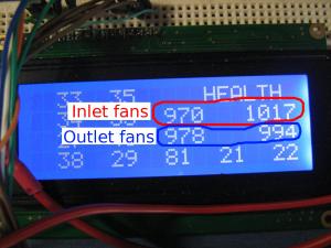
The main difference with the other circuit used for the Cooler Master fans is the rpm feedback filtering. I used a Schmitt trigger to make the pulses rectangular. The R7-R8 voltage divider will make the 12 volts output of the ST circuit capable to be driven to the PIC input, and the D2 is a 5.2V zener diode in case that something goes wrong. If you are sure about the 741 and all the things around it, then this diode can be omitted. In case that you try to copy this circuit with different fans (remember i use Zalman), then you may consider changing the ST thresholds or the R7-R8 voltage divider. One point that you need to take into account with the voltage divider: The logic 1 of the St output is 12Volts, while the logic 0 is unfortunately NOT 0 volts. It is about 2 to 3 volts, depending on the speed and the type of this fan. So, when you calculate the resistors for the voltage divider, do it according to the LOGIC LOW instead of the LOGIC HIGH. After all, the Zener will keep it down to 5 volts. For your calculation, you need to know the Input HIGH Voltage characteristic. For the PIC i use, this is 2 Volts. During my first experiments, i failed to receive rpm feedback not because the voltage on the pin was not high enough (to read logic HIGH), but because during the LOW level of the pulse, the voltage was slightly above 2Volts, so the PIC received always HIGH. To make the circuit more "Universal", you could add a switching transistor. The results The circuit above is just for one fan. On my PCB, i host two identical circuits together. The other 2 fans use separated controlling circuits. And this is what i got on the first run: 
Just for the record, i have increased the rpm threshold on the controllers to 80rpm. This means that if i set the rpm for example to 1000 (as i did during the first test), the controllers will consider the fan "centered" for rpm values between 920 and 1080. Comments
|
|
 Contact Contact
 Forum Forum
 Projects Projects
 Experiments Experiments
 Circuits Circuits
 Theory Theory
 BLOG BLOG
 PIC Tutorials PIC Tutorials
 Time for Science Time for Science
 RSS RSS
Site design: Giorgos Lazaridis © Copyright 2008 Please read the Terms of services and the Privacy policy |