The circuit on the testing bench, assembled on a breadboard
A friend of mine asked me for this circuit. He plans to make an automations with PLC in his house, and he wants to have a couple of dimmers for his lights. The challenge was to control those dimmers with an analog PLC output. He asked me for a simple - microcontroller free circuit to do the job.
The control signal
The circuit is designed to work from an analog output of a PLC. Here you can see the Mitsunishi ALPHA with an I/O emulator connected to the circuit
The first thing that comes to someone's mind when thinks of a dimmer, is a potentiometer that controls the light intensity. If a potentiometer is used, things can be very easy. Tons of different circuits can be found around the net. Others are very precise, others are not so stable. But the control of this dimmer is a DC voltage level.
The specific PLC that he will use has 4 analog outputs. Each output can be programmed to deliver any voltage between 0 and 10 VDC, with 0.01 voltage step. He plans to have a mimic program with 4 slide bars or buttons displayed on a touch screen connected to this PLC, and control the lights from there.
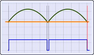
The first thing that came to my mind was a comparator circuit. I would have the mains power through a transformer transformed to 9VAC, and then full rectify this signal. Then, using a comparator, i would compare this signal with the control signal from the PLC. Whenever the 9V signal was higher than the control signal, the output of the comparator would go high and it would drive the gate of the TRIAC (through an optocoupler of-course). Although this sounds a good idea, it is actually completely false approach. Look what will happen:
The control voltage is minimum
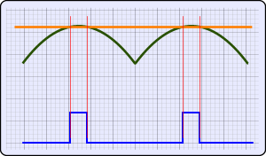
The control voltage is maximum
When the control signal is minimum, the comparator's output will send the trigger pulse to the TRIAC's gate at the very beginning of the waveform. This will send full power to the light. As the control voltage is increased, the trigger will delay more and more and the light will gradually dim. Until here everything looks normal. But when the control voltage is at maximum, the trigger pulse can only be located at the middle of the waveform, as is shown on the right image above! The triggering pulse will never delay more than half a semi-period. This means that the light will never dim less than half of the power. The triggering circuit needs to be completely different!
A more advanced triggering idea
The 555 will generate a pulse, with a delay. This delay will start count from the time a zero-cross detection pulse is occurred, and the delay time is set from the DC voltage level applied on pin 5 of the 555.
I have a really good zero-cross detection circuit posted in the dimmer theory page. This circuit will generate a clean rectangular positive pulse whenever the waveform crosses the zero-point. The only thing i had to find out, was how to make a delay-ON circuit that would start counting from this pulse. Moreover, this delay circuit had to be controlled from a DC voltage level.
To tell you the truth, the on-delay circuit was not very hard for me to find one. Actually, my mind went directly to the 555 timer connected as monostable circuit. The trigger input of the 555 (pin 2) would be connected to an inverted output of the zero cross detection circuit. A properly selected RC net would create a fixed delay.
And right here comes another challenge. The delay of the 555 must be variable and controlled with a DCV signal. The 555 timer is not the most common and most used chip ever just by luck. If you look at the 555 theory page, there is the internal diagram of the chip. You will notice that the upper comparator has it's reverse-input pin coupled with a chip-pin, and this pin is the pin number 5. Actually, the pin's name is pretty much self-explanatory. It is named "Control Voltage". If you apply voltage to this pin, then the voltage level of the reverse-input of the upper comparator, and the level of the non-reverse-input of the lower comparator is affected. When the 555 is connected as monostable multivibrator, the upper comparator will monitor the capacitor's voltage. By changing it's reverse-input voltage level, this affects on the delay of the timer!
In other simple words, the input voltage is coupled (through a limiting resistor) directly to the pin 5 of the 555 timer. The higher the voltage, the more the delay from the 555.
The Circuit
The circuit is as follows:
The mains AC voltages is transformed to 9VAC through the transformer. the signal is rectified with a full-wave bridge rectifier. Immediately after the rectifier, the signal is driven to the zero-cross detection circuit. A large capacitor (C1) is used to smooth a part of the rectifier's output power. This will be used as the power supply of the rest of the circuit. The diode D1 is very important. Without this diode, the signal that is drivern to the zero-cross detection would be smoothed as well, and the zero-cross detection would be impossible.
The output of the zero-cross detection is directly sent to the trigger input of the 555 timer. The control voltage is driven to teh input 5 of the 555 timer. The rheostat R9 is used to control the maximum delay of the 555 timer, so that with maximum control voltage, it will NOT exceed the length of a semi-period, otherwise the light will be turned into a crazy-disco-light. A reader [PUNiSH3R] posted a comment (bellow) regarding this component. When i designed this circuit, i had it on a breadboard for test, and i had a bit potentiometer and an oscilloscope, so i could adjust the circuit easier. But as PUNiSH3R suggested, better use a multi-turn potentiometer with higher precision.
The output is then inverted with the transistor T3 and the signal is driven to the P gate of the optocoupler. the optocoupler is used to have complete galvanic isolation between the control circuit and the power circuit. The power circuit uses a BT136 TRIAC to control the load. This TRIAC is capable of driving a 4 amperes load at 600 volts. Feel free to use a more powerful TRIAC.
A Test-Run
As always, the circuit is tested in the PCB Heaven techlabs. We present you a series of images from the circuit in operation. Notice the intensity of the 600 Watt lamp, and the oscilloscope's screen. The green waveform is the output of the bridge rectifier. The blue pulses comes directly from the output of the zero-cross detection circuit. These pulses are driven to the trigger pin of the 555. Finally, the yellow line is the triggering pulse generated from the 555 timer:
For this demonstration, the control voltage was generated from a 5K potentiometer. Actually, any kind of DC voltage level generator can be used to control this circuit. It could come from an LDR voltage divider, from a potentiometer, from a PLC etc etc etc.
This video demonstrates the circuit in operation. The control DC voltage is generated with a 5K potentiometer. The whole operation looks like a normal dimmer:
The following video demonstrates this circuit, interfaced to the Mitsubishi ALPHA PLC. The up/down control is currently made with toggle switches:
Bill Of Materials
Resistors
R1
Resistor 10 KOhm 1/4 Watt 5% Carbon Film
R2
Resistor 1 KOhm 1/4 Watt 5% Carbon Film
R3
Resistor 4.7 KOhm 1/4 Watt 5% Carbon Film
R4
Resistor 100 KOhm 1/4 Watt 5% Carbon Film
R5
Resistor 10 KOhm 1/4 Watt 5% Carbon Film
R6
Resistor 1 KOhm 1/4 Watt 5% Carbon Film
R7
Resistor 4.7 KOhm 1/4 Watt 5% Carbon Film
R8
Resistor 1 KOhm 1/4 Watt 5% Carbon Film
R9
100 KOhm Linear multiturn precision potentiometer
R10
Resistor 1.5 KOhm 1/4 Watt 5% Carbon Film
R11
Resistor 1 KOhm 1/4 Watt 5% Carbon Film
R12
Resistor 1 KOhm 1/4 Watt 5% Carbon Film
R13
Resistor 1 KOhm 1/4 Watt 5% Carbon Film
Capacitors
C1
1000 uF 16V Electrolytic Capacitor
C2
0.1 nF Ceramic Capacitor
C3
1 uF 16V Electrolytic Capacitor
Diodes
D1
1N4001 General Purpose Diode Rectifier
B1
2W10M Single Phase 2 Amps Silicon Bridge Rectifier
Transistors - TRIACs
T1-3
BC548 Switching and Applications NPN Epitaxial Transistor
T4
BT136D Sensitive gate TRIAC
ICs
IC1
555 Timer
OK1
MOC3021 Random Phase Optoisolator TRIAC Driver Output
Using this circuit for professional use
No, i would not recommend this, but it seems that a forum user named vertebro from Buenos Aires,Argentina, was willing to break all the rules! He managed to utilize this circuit to control a professional Automatic Textile Press with 3 channels of 3x1500 Watts load each. Here are two videos from this mod:
And here are some pictures (click on each one to enlarge):
Hi Giorgio,
have found your circuit here: http://alfadex.com/2014/02/dimming-230v-ac-with-arduino-2/ with no mention to your original article.
Anyway, i would like to use this circuit with Arduino Analog Output (Max 5VDC) how can i adapt it to work with ?
Using a 5VAC transformer? Or using a transistor on the input line to drive 12 VCC with arduino?
Thank You.
At 19 June 2015, 15:21:11 user Spee wrote: [reply @ Spee]
Can you explain to me why I am getting uneven length on the wave at the low setting. Have made another zerocrossing then what you show here, but it is not the zero-cross there is something wrong with. I try to get it to work down to 0% and I also can, but each triggering pulse from the 555 has in time a difference about 4 times larger in every other pulse than the previous pulse, this only when I get 2-8 % from zero. Is it the components tolerance?
@Cytrek the transformer is 9VAC so the DC value is 12.7V
At 21 February 2015, 14:45:24 user Cytrek wrote: [reply @ Cytrek]
@Giorgos Lazaridis hello Sir, can you tell me what is the value of VCC that is used in the circuit? and for BT136D, is main terminal1 and main terminal2 interchangeable? I want to make a dimmer controlled by LDR and Microcontroller for my project in school. Thanks
@ravi No, it has linear response to trigger angle, but not to output power due to the sin input
At 7 December 2014, 5:56:11 user ravi wrote: [reply @ ravi]
hello sir
i have another query
is this circuit have linear i/p between 0 to 10 volt d.c ?
because s7 400 plc gives 0 to 10 volt analog output (example PQW 512)
so where i have to connect this o/p with this circuit?
where to connect CNTR (pin no 5) of ic 555?
i want to control it with pid block so....
REGARDS
RAVI
At 6 December 2014, 10:30:39 user ravi wrote: [reply @ ravi]
thank you so much.
my planning is to control inlet water flow by controlling 230v A.C motor with this circuit and s7 400 plc and i am also planing to use pid controller block of PLC for linear output.
lets hope will work fine........
At 6 December 2014, 6:38:01 user ravi wrote: [reply @ ravi]
hello
thanks for this wonderful website.
can i use this circuit for motor control using siemens plc s7 400? in the plc 0 to 10 volt control analog output so.
At 27 September 2014, 20:46:34 user johann wrote: [reply @ johann]
Hi Giorgos, i'm using a 120VAC to 12V (1A) transformer and the diode bride (quite the same one used in your circuit) -2W10-, is heating up until smoke can be seen. Do you know why, is it hapening?, actually, just the circuit until D1 and C1, decoupling the zero cross detection and beyond already presents this problem. Thanks in advance
Hi Giorgos
From all the posts it seems like this is a great circuit you put together. I would like to use your circuit with a 0-4V DAC control voltage and a 5Vcc supply. Do you think it would work for this? Instead of the 0-4V DAC I could also use a 0-5V pwm - would this work as well?
@Chipie Unfortunately it goes one trafo for each phase, 3 transformers in total. Unless if you use a microcontroller which can calculate the phase shift.
For a 0-5voltage input you will have to make a transistor interface instead. Or an op-amp amplifier of some sort. Something to translate the 05 to 0-10
Hello Giorgos,
I have two questions, I want to use this cirquit to regulate heating coils in a 3 phase setup, means one coil per phase. Do I have to feed the transformer from the same phase because of the zero cross detection or can I use one transformer for all three and feed it with one of the phases??
Second if I make R13 500 ohms can I use 0-5 volt??
sir i have two doubt in voltage controlled AC light dimmer circuit..
1. how much voltage u are giving to ic555 timer.??
2. where the pin 5 of ic555 timer is attached in the circuit?? i mean from where the control voltage input is taken to pin5 ???
Hello i made this circuits and works perfect.
I want to use a transformer 15 Vac and i want two place 7812.
http://img34.imageshack.us/img34/1896/bqoz.png
I place Ci to the output of 7812 but ,doesn't work.
Am i missing something?
The bulb light all time 100%.I cannot dim it
@PHB The transistor is used to drive the LED of the optocoupler. The 555 has enough current for this particular optocoupler, but just in case...
C2 is typical bypassing capacitor. The resistors are calculated according to the transistors to bias them properly.
At 27 October 2013, 15:41:51 user PHB wrote: [reply @ PHB]
Hey there, The circuit works beautifully!! However, I would just like to know a few things: In regards to the zero crossing detector- how was the resistor and capacitor values chosen? Also, if my voltage control is at a maximum the light is off and when it is at a minimum the light is on (I assume it is because of the inverter at T3 ) why would one do this?
@Giorgos Lazaridis: Thanks, I've tested the wires in the wall and i have one plus and two minuses (it's a 2 bulb switch). Thanks. I will try to separately power the circuit and in this case it should work i guess.
@Islam Qabel 1. Optocoupler is for your own safety and the sake of the circuit. You need to study the 4 quadrants of the TRIAC first to find out the current demands for your needs. Then yes, you can do this connection.
I tried your circuit, works great standalone. My problem is i want to hook it up to a wall switch (in fact replace it). Could anyone please let me know if that is possible and how to wire up the pins? The goal is to have it controlled by arduino.
1) Can i connect the output signal for collector of BC548 directly to the gate of BT136 instead of using Opto-triac ? I made simulation using Proteus and it was successful but practically what do you think?
I suggest that you can generate the zero-cross detection signal using 4n25 opto-coupler by connecting terminal of the bridge to pin 1 through 220 or 330 ohm resistor, the - terminal to pin 2, pin 5 to Vcc and pin 4 is connected to GND through 1k resistor....take the output signal from pin 4 and apply it directly to pin 2 on the 555 timer. i think it will be more better.
@Giorgos Lazaridis hello sir , i set the all components according to the exact circuit diagram . i give a 230v ac phase to my ic 555's 5th pin(control voltage) but lamp is not glow and also my ic 555 timer is heavily heated, please help me sir what's wrong with me?
At 22 June 2013, 3:41:32 user qao wrote: [reply @ qao]
btw - I found this DC controlled dimmer product online. Is this similar to your circuit in any way? Page 15 of the manual link has the circuit diagram. This circuit claims to work from 0-5V. Thanks.
@qao I'm not sure what changes you have to make. If the Vcc is 9V, then you need something close to 9. So you have to redesign it for 5V
At 18 June 2013, 20:14:41 user qao wrote: [reply @ qao]
Nice circuit. Can this circuit be controlled using 0 to 5V instead of the 0-10V mentioned or what changes would need to be made? I would like to control a lamp from the 0-5V output of a d/a converter. thanks.
At 11 June 2013, 2:17:36 user Paul wrote: [reply @ Paul]
Thanks a lot dude your project help me with some problems i had, after i finish my project of a temperature control i will post it too
@Giorgos Lazaridis
It worked ok! is there any place so i can post a diagram
of what i need to do?
with one circuit,i need to have 3 channels dimming 5000w each.
3 switches to activate each channel ,just one potentiometer for all channels,but it must work with a three phase ac source due to the power needed.(neutral 220v 220v 220v)
can i just add 2 more optocouplers an triacs ?
Do triaCs need some RC conected in parallel to pins a1 and a2?
which is a1 and a2 pin in your dimmer diagram?
Thanks a lot for your answer!
@vertebro I bet its power dissipation. At 20A you need to dissipate some 25Watts of power which is the same heat that your soldering iron provides. Have you used proper heatsink? Maybe a small fan?
Hi Giorgos,writing from Argentina!
I just built your dimmer and i control it with a 5k pote,
it works really well,but i have a problem:im dimming halogen 220V,1500wlamps for flashing and curing inks. when I connect just one lamp it work fine,then add another,fine(3000w)finally i connect one more,(4500w,20A)turn it on(from the main switch and the triac got shortcircuit and from there the lamps remain full on.
The triac im using is a BTB 41-700B What can it be my problem??
Some help woul be very appreciatted!!!!
AMAZING WEBSITE!!! is the only place where i found this particular circuit,im trying to emulate a plc tri phase pic controlled that came in a flash i had from Portugal
@Steve Correct - The voltage must be AC, and the gate pulse must not exceed a half-period's length.
At 20 October 2012, 6:59:36 user Steve wrote: [reply @ Steve]
I ran across this in search of a dimmer that is 555 based, but isn't for lamp control, and isn't for sine wave either. Load is still resistive (heating element), but power source is MSW inverter. Appears to me it would work as such, but I'd like to be sure before I build it. All it cares about is that there's a zero cross and that the one shot period is shorter than each polarity flip, correct?
I would like the brightness and input voltage to be proportional. In other words as the input voltage increases the lights will get brighter. What change do I need to make.
Alao, could you include a higher resolution schematic? I can't read it.
@pantelis you need first to add an inductor to the output. read the datasheet of the MOC optocoupler. It has detailed explanation how to use this with inductive loads.
Hi nice circuit, can i use this circuit to control a motor 850W from a drill 230 volts
thank you
At 27 February 2012, 11:23:24 user Joseph wrote: [reply @ Joseph]
It will be easy to tune if you change the C3 to 0.1uF (104) & (R8 R9) = 68K.
Of course if you add a pot to the voltage control pin you cannot use its full range from Vss to Vdd.
If its CMOS 7555 & supply is 5V.The effective range will be 0V - 4V.Something above 2/3Vss will get bad results.So you need to add a fixed resister in series with the potentiometer if you wish to control pots full range.Without the fixed resister you will get bad behaviour on the lamp.
@Joseph oh i understand what you mean. I did not faced such problems at all. At very low settings, the light barely had a red tungsten wire. It worked perfectly well. Major problem of this circuit is the adjustment. You will get this problem yo mentioned with a bad adjustment. In the video you can see how smooth it operates. As a matter of fact, i designed this circuit because a friend of mine said that a 555 cannot work as a dimmer.
At 27 February 2012, 10:39:06 user Joseph wrote: [reply @ Joseph]
@ Kammenos
Hi that%u2019s what I%u2019m also saying. This circuit can vary only the delay which is after the zero cross occurs. After timeout this will fire the gate signal until next zero cross occurs.
I asked because when we designing microcontroller based dimmers we normally give a small trigger pulse to the triacs gate like 5uS time. we don%u2019t keep this trigger pulse until next zero cross occurs, after the small trigger pulse applied to the gate the triac will turn it off by itself when the waveform nearly closer to zero cross.
It%u2019s nice the your zero cross circuit will make low pulse just before the zero cross happens (that%u2019s the secret) so the whole timer will be renew & the triac will be switched off.
How was the smoothness of the bulb when the brightness is in the lower end!!
I hope you get an extremely smooth light levels & no more flickering %uF04A
@Joseph hello. As a matter of fact, this was the idea when building this circuit on the first place. The trigger pulse will start on with a certain delay after zero cross, and will end little before the end zero cross. Why you want to change the delay? This is not some kind of PWM.
At 27 February 2012, 4:10:49 user Joseph wrote: [reply @ Joseph]
Hi @ Kammenos
I simulated this circuit & its working fine. One thing to inform you, it does not adjust the pulse width of the high pulse independently.
In other words it cannot change the width of the pulse that triggers the triac gate or MOC3021.
Ex: if the lamp is half brightness then this circuit will trigger the gate until next zero cross occurs.
Again this circuit can only adjust the delayed time after zero cross occurs.
You cannot adjust both delay off time & high pulse time independently.
Did you get what I mean?
@Zamboni hmmmmm good question. normally yes, this would work, but better use this one instead:
http://www.pcbheaven.com/userpages/Flexible_555_LED_Pulsing_Circuit
if you make it work, send us a video to see the results
Would it be possible to use this circuit, http://pcbheaven.com/circuitpages/555_Breathing_Pulsing_LED/ as the control voltage input to create a series of breathing 220v lamps?
@Joseph that's right, i used pin 5 to avoid using a secondary one-shot 555. For the test i used a potentiometer as a voltage level, but i also used the analog output of a Mitsubishi Alpha PLC. You can interface other voltage sources as well.
At 11 January 2012, 11:26:24 user Joseph wrote: [reply @ Joseph]
@ Kammenos
Now I got it, you controlling both times.ON delay & the ON time.So you need to use the pin5 as well.From your pictures looks like you have connected a potentiometer to that pin.Pots side pins to Vdd & Vss & center pin to pin5.
Cant you ground the pin 5 (control voltage pin) via a 0.01uF capacitor & make the maximum monostable delay 10mS? So anybody can dimm the lamps by adjusting the potentiometer.
most of the guys messed up with the pin5 control voltage & where to connect it!!
Hi
I have built the circuit and I have a variable pulse width at pin 2 of the MOC3023. The voltage also vairies the pulse width so all looking good except no ilumination of the lamp at all. It all checks out as far as wiring . I have replaced the opto isolator but no change. Any suggestions? The Triac was o in another circuit I built it is a BTA20. Many thanks for you time.
At 8 November 2011, 18:06:09 user Alex wrote: [reply @ Alex]
@Alex what is the LDR output? Voltage or current? You may wanna use the forum (http://www.pcbheaven.com/forum/) to post some images or details for your project
@Suresh you can connect the triac on a small pre-drilled PCB. The rest of the circuit requires only a tiny amount of current. If you see my pictures, during tests, i ha a big (i think 600W) lamp connected and all parts including the triac were on the breadboard without any problem. But i cannot share a suggestion for this.
At 8 November 2011, 0:36:10 user Alex wrote: [reply @ Alex]
I'm trying to adapt your circuit to make a device that will feed my lamp. I have a laser diode that will light a LDR. The LDR will trigger a fade in fade out circuit.
The problem is when i have to modify the Control Voltage in order to light my lamp in a fade-in effect. This is where i got stuck and i really don't know what to do.
I'm simulating your circuit with LTSpice and Multisim and the results are different (especially when modifying the potentiometers). I would really appreciate if you'll give me some ideas about this circuit.
Thanks!
At 7 November 2011, 13:13:23 user Suresh wrote: [reply @ Suresh]
Hi,
We are using a normal breadboard for this circuit. In this link http://en.wikipedia.org/wiki/Breadboard , it is given that specification of breadboard is 5Watts. Is it safe to use a breadboard for this experiment as it operates at 600Watts? Thanks in advance.
Hi there, this looks like a great circuit to have digital control over lighting. However can this same circuit control a 220v 25w fan motor?
If not directly can you please suggest a modification to do just that. I'm trying to control the speed of an AC vetilation fan.
@kaypee which potentiometer?The LDR (one only) must be combined with a resistor, make a voltage divider, the output of which must go to Control Voltage Input. Otherwise, funny things will happen.
Kammenos, I tried the basic circuit with using directly the 220v supply and Triac(a simple fan regulator circuit). I placed 3LDRs in series with potentiometer.But its doing the wrong work. Actually,when light is falling on it , it is making the bulb go brighter.How can I invert the effect?
@kaypee if you remove the transistors it will not work. The circuit cannot be simplified, unless you find another method to do the zero-cross detection, and replace all the part from R1 to R7.
If I remove the 2 transistors before the 555 will the circuit work.As they are just doing amplification work??Can you simplify the circuit a liitle more??/
@kaypee a you mean the middle terminal and one of its side... yes, sure. they must be connected together. What do you want to know about control voltage input? It is a DC voltage from 0 to VCC. It is the voltage that controls the dimming.
First you need to see if pulses arrive at pin 2 of 555. Then you need to see if pulses arrive at base of T3, and then if pulses arrive at pin 1 of OK1. If pulses arrive at all these points, then you can go on and check the triac.
Then what that symbol means???That how R9 POTENTIOMETER is to be connected and also tell me about the control voltage input.I used multimeter and found out that there was no current going after Triac.
I hadn't used diode D1 and capacitor C1. I just had given a separate Vcc through a 9v battery.Could this be the reason. To what value the fixed potentiometer is to be fixed.I had used a filament Bulb as source.
I will mail the video of the circuit.
Kammenos, I tried your circuit by giving Vcc through a 9V battery. But the bulb was not glowing.Please help me.I tried for the manual dimming using a 10k Potentiometer.I had used 4 diodes as rectifier. Every IC was placed correctly.Please help me what could be the possible reasons of failure.
Can I do one thing. I will give the input for zero cross detection after bridge rectifier and could give the Vcc separately through a DC source 9V.
It will also work I suppose.
I tried the circuit in my electronics lab using a 220to 9v (0.5ampere)transformer. And what happened is the capacitor C1 BLOWN away.
What could be the possible reasons.?
And also I m using BC558 IN T3 as I am running short of BC548 is there any problem in that?
Hi everyone.. I have setup this circuit in the multism and I could not work it some basic problems I think. first where the connction between two sides of the lamb and where i should connetc the control voltage on the timer. most of the important although I changed the value of potentiometer value the output power on the lamb did not change.. Can anybody help me this situation, please?
@kaypee i do not use a voltage regulator either. And no, you cannot use a simple adapter as you need the AC for zero cross detection. The 100K potentiometer may be changed only if you know which value to use. You can add testing resistor in series and find out. eg: use a 10K potentiometer with series 10K or 22K or 48K resistor.
and can I use a siple adapter instead of using TRANSFORMER AND RECTIFIER.
and is there any need of using 100kohm Potentiometer?Can\'t we use a smaller rating potentiometer?
Exactly, thats what I want to make. An automatic light regulation according to the intensity of Sun's Light falling in a room.
Thanks a lot Kammenos, I will try this and let you know of its success.
@Kaypee now i understand what you want. Do not replace R9 with an LDR at all. What you need to do, is to make a voltage divider with the LDR and another potentiometer, and then drive the output voltage to input "Control Voltage Input" marked in the schematic. This is the correct way to do it.
Regarding the voltage divider, look at thic circuit:
http://pcbheaven.com/circuitpages/PIC_DCV_Controlled_AC_Dimmer/
There are 2 potentiometers, R3 and R7. You will replace R7 with your LDR, and then you will drive the output of R3 to the input of your circuit. This will make a variable DC voltage according to the light brightness on the LDR, and finally it will control the dimmer brightness. Your potentiometer R3 can be 10K potentiometer and the LDR can be for example a 1-100K LDR or any other. No problem.
If I want to just demonstrate that light is getting dimmed and brightened and don't take into consideration by which amount. Then can you suggest me which LDR and which trimmer should I use.Actually I have taken a project and just want to demonstrate it so please help me in completing the project.Thank you.
dbyrne, you can use your transformer as long as it provides enough voltage (6 volts and above). The bridge rectifier has to be full wave rectifier. Regarding the on-off that you mention, i do not really understand what you mean.
Hey. This is exactly the circuit I require for a project I am doing, the LDR will determine the voltage control. Can this circuit be simplified, as i have my own transformer and brige ect already built. Will this circuit prevent the lights from continously switching on and off. I am using a PIR so when movemnent is detected only then will the lights turn on, but they wil only turn on by being controlled by the LDR.
PUNiSH3R, i had not though of that, because i did the setting with the help of my oscilloscope, and also i had a large potentiometer, which i could easier set to a position, rather than trying to set a small trimmer with the screwdriver. Thanks for noticing. I added this in the documentation above as well.
Thanks for the circuit and great description. I built it in an afternoon and it operates perfectly with a Teccor Q6008L5 Triac (which is a BT137 equivalent). I am using it with another one of your projects, the acrylic bender, which I am currently completing.
If I may make a suggestion to other builders: try and use a multiturn linear potentiometer for R9. It's not impossible to tune the circuit with a standard trimmer, but a 10- or 15-turn will make it noticeably easier to hit the sweet spot where the lamp stops flickering across the entire control range.
Thanks again for the circuit, the project and the website!
I've just built your circuit and I tried to dim both, fluorescent lamp and a bulb lamp, as you mentioned, CFL did not work, on the contrary bulb lamp lighted up.
At 19 April 2010, 22:04:31 user jared wrote: [reply @ jared]
Would you be able to make this circuit using a micro-controller for us to look at?
Reason I ask is there is a lot of lighting controllers out there that output 0-10vdc for the control but nothing really to describe how to convert that over to PWM for use with a HB LED driver to dim them.
I would really like to see the circuit you describe and host it in my circuit pages. It is very interesting.
I made this circuit about a month ago in a hurry, and worked fine. I told you that from the PLC i used 5 to 10VDC. If i wanted to have 0-10 from the PLC, then YES, i need buffering. I do not remember having ANY trouble adjusting the circuit at all. I am waiting some components and i will make a project with a 4-channel dimmer, that will be this exact circuit multiplied by 4. You need to follow a specific procedure to adjust it,NOT difficult at all, but specific. Unfortunately, i did not post this procedure on the first time, stupid of me. If i am remember correct though, you set the MAX DC voltage input, and then using the R9 you go to the point that you have max luminosity and no flickering. That's all. With the PLC for example, i set it to 10 VDC and then adjusted R9 to have steady max light. Then, reducing the PLC voltage, i found out that from 5 volts and bellow i had no luminosity.
I have eventually given up on this circuit. The control circuitry feeding R13 needs buffering due to the input configuration of the 555, and setting up via R9 over the range of control voltages proved impossible.
A much simpler and stable circuit is to use the zero-crossing detect circuit to control a one-transistor sawtooth generator (of twice mains frequency). This and the d.c. control voltage are applied to the inputs of an op-amp, whose output is fed to the buffer of the opto-triac.
Whichever circuit is used, a snubber network (100 ohm resistor in series with 100nF capacitor) connected across MT1 and MT2 of the triac will prevent rate-effect mis-firing.
You are right about the control voltage. The min and max levels have nothing to do with VCC. I test it with 5-10vdc from a PLC output, and 0 to 12V with a potentiometer. R9 was correctly adjusted! With R9 you set the max level. Beyond this, the delay of the 555 is longer than the semi-period of the ACV and funny things may happen.
R8 is 1KOhm and usually should not be changed. Changing R8 will not hurt anyone though. R9 may indeed need to be changed for the ease of adjustments. It has to do mainly with the control voltage level.
To set up the circuit, I set R9 to minimum value, with the control voltage at maximum (which might not necessarily be equal to Vcc). I then increased R9 for maximum stable pulse-width. Beyond this point the waveform \"flipped\" to a regular 1:1 m/s ratio pulse-train.
In my hook-up, for some reason, I needed a value for R8+R9 of only 3.5kΩ so I used R8=2.7kΩ and R9=1kΩ.

 Home
Home
 Projects
 Experiments
 Circuits
 Theory
 BLOG
BLOG
 PIC Tutorials
 Time for Science


 Contact
 Forum
Forum
 RSS
RSS


 Reddit this

