To learn and understand the principle of operation of the stepper motors, to me is very important. A stepper motor is always the simplest, cheapest and lighter solution for accurate positioning systems. It this article, i will explain how the stepper motors are made, and how they work. It is necessary to have some very basic knowledge for the operation of DC motors to follow this article. I suggest you read first How DC Motors are made and how they work.
What is a stepper motor?
First of all, a stepper motor is a motor. This means, that it converts electrical power into mechanical power. The main difference between them and all the other motors, is the way they revolve. Unlike other motors, stepper motors does not continuously rotate! Instead, they rotate in steps (from which they got the name). Each step is a fraction of a full circle. This fraction depends mostly from the mechanical parts of the motor, and from the driving method. The stepper motors also differs in the way they are powered. Instead of an AC or a DC voltage, they are driven (usually) with pulses. Each pulse is translated into a degree of rotation. For example, an 1.8o stepper motor, will revolve its shaft 1.8o on every pulse that arrives. Often, due to this characteristic, stepper motors are called also digital motors.
First of all, you may want to see the videos with the 3d model of a stepper motor, that i explain how it is made and how it operates:
PART 1
PART 2
A very basic stepper motor
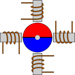
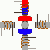
As all motors, the stepper motors consists of a stator an a rotor. The rotor carries a set of permanent magnets, and the stator has the coils. The very basic design of a stepper motor would be as follows:
There are 4 coils with 90o angle between each other fixed on the stator. The way that the coils are interconnected, will finally characterize the type of stepper motor connection. In the above drawing, the coils are not connected together. The above motor has 90o rotation step. The coils are activated in a cyclic order, one by one. The rotation direction of the shaft is determined by the order that the coils are activated. The following animation demonstrates this motor in operation. The coils are energized in series, with about 1sec interval. The shaft rotates 90o each time the next coil is activated:
Driving modes
In this section, i will explain the various ways that the coils are energized, and the results on the motors shaft.
Wave drive or Single-Coil Excitation
The first way is the one described previously. This is called Single-Coil Excitation, and means that only one coil is energized each time. This method is rarely used, generally when power saving is necessary. It provides less than half of the nominal torque of the motor, therefore the motor load cannot be high.
This motor will have 4 steps per full cycle, that is the nominal number of steps per cycle.
Full step drive
The second and most often used method, is the Full step drive. According to this method, the coils are energized in pairs. According to the connection of the coils (series or parallel) the motor will require double the voltage or double the current to operate that needs when driving with Single-Coil Excitation. Yet, it produces 100% the nominal torque of the motor.
This motor will have 4 steps per full cycle, that is the nominal number of steps per cycle.
Half stepping
This is a very interesting way to achieve double the accuracy of a positioning system, without changing anything from the hardware! According to this method, all coil pairs can be energized simultaneously, causing the rotor to rotate half the way as a normal step. This method can be single-coil or two-coil excitation as well. The following animations make this clear:
Single-Coil excitation
Two-Coil excitation
With this method, the same motor will have double the steps per revolutions, thus double the accuracy in positioning systems. For example, this motor will have 8 steps per cycle!
Microstepping
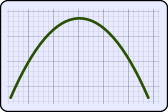
Microstepping is the most common method to control stepper motors nowadays. The idea of microstepping, is to power the coils of the motor NOT with pulses, but with a waveform similar to a sin waveform. This way, the positioning from one step to the other is smoother, making the stepper motor suitable to be used for high accuracy applications such as CNC positioning systems. Also, the stress of the parts connected on the motor, as well as the stress on the motor itself is significantly decreased. With microstepping, a stepper motor can rotate almost continuous, like simple DC motors.
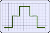
The waveform that the coils are powered with, is similar to an AC waveform. Digital waveforms can also be used. here are some examples:
Powering with sine wave
Powering with digital signal
Powering with high resolution digital signal
The microstepping method is actually a power supply method, rather than coil driving method. Therefore, the microstepping can be applied with single-coil excitation and full step drive. The following animation demonstrated this method:
Although it seems that the microstepping increases the steps even further, usually this does not happen. In high accuracy applications, trapezoidal gears are used to increase the accuracy. This method is used to ensure smooth motion.
Stepper motor types
Permanent Magnet Stepper Motor (PM)
The first and most basic type of stepper motors is the Permanent Magnet (PM). The rotor of the PM motor carries a permanent magnet with 2 or more poles, in a shape of disk. The operation is exactly the one described above. The stator coils will attract or repulse the permanent magnet on the rotor and will generate the torque. Here is a sketch of a PM motor:
PM stepper motors have usually step angle from 45o to 90o.
Variable Reluctance Stepper Motor (VR)
The VR motor does not have a permanent magnet on the rotor. Instead, the rotor is made of soft iron, and performs a teethed disk like a gear. The stator has more than 4 coils. The coils are energized in opposite pairs, and will attract the rotor. The lack of a permanent magnet has a negative affect on the torque that is significantly decreased. But it has a great advantage. These motors have no detent torque. The detent torque, is the torque generated by the rotor permanent magnets that are magnetized to the stator's armature, when no current flows within the coils. You can easily understand what this torque is, if you try to rotate an unconnected stepper motor by hand (NOT a VR stepper). You will feel the distinctive "clicks" of each step of the motor. Actually, what you feel is the detent torque that pulls the magnets against the armature of the stator. Here is an animation of a VR stepper motor in operation:
VR stepper motors have usually step angle from 5o to 15o.
Hybrid Stepper Motor
The hybrid stepper motors are named so, because they combine the characteristics from both VR and PM stepper motors. They have excellent hold and dynamic torque, and very small step angles, from 0.9o to 5o, giving them A+ in accuracy. Their mechanical parts can rotate at high speeds relatively to the other stepper motor types. This is the type of motor used for high end CNC and robots. The major disadvantage is the cost.
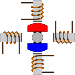
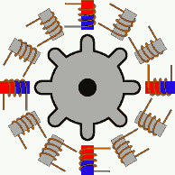
A typical 200 steps per revolution motor, will have 50 North and 50 South poles, with 8 coils (4 pairs). Because such a magnet cannot be manufactured, an elegant solution has been given. There are actually 2 separate disks, each one with 50 teeth. A permanent cylindrical magnet is also used. The disks are welded one on the North and one on the South pole of the permanent magnet. Thus, one disk has North pole on its teeth and the other South. The trick, is that the disks are placed in a way that if you look them from above, you will see one disk with 100 teeth! The hills of the first disk, are aligned with the valleys of the other disk.
A permanent magnet with 50 North and 50 South poles is not possible to be manufactured...Therefore two disks are placed on top and bottom of a cylindrical permanent magnet
The hills of one disk are aligned with the valleys of the other. If you look the disks from above, it will be like looking a 100-teethed disk with 50 north and 50 south poles! An elegant solution!
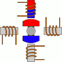
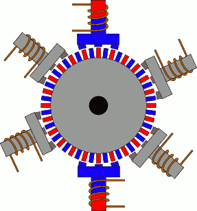
The following animation shows a hybrid stepper motor with 75 steps per cycle (5o per step). Worth to notice that the 6 coils are in pairs of two, each one with its opposite coil. Although someone would expect to find these pairs with angle difference of 60o, it is not so. If we suppose that the first pair is the most top and most bottom coil, then the second pair is with angle difference of 60+5o from the first, and the third 60+5o from the second. This angle difference is the reason why the motor moves! Full and half stepping can be applied, as well as single-coil excitation for power saving. In this animation i use full step drive. With half step drive, the steps are increased to 150!
Don't try to follow the coils to see how it works. Just focus on one coil and wait. You will notice that, whenever this coil is actuated, there are 3 North poles (red) 5o back, that are pulled to the rotation direction, and another 3 South poles (blue) 5o front that are pushed to the rotation direction. The coil that is actuated is always between the North and South poles.
Coil connections
Stepper motors are actually multiphase motors. The more the coils, the more the phases. The more the phases, the smoother the operation of the motor and the higher the price. The torque is irrelevant to the number of phases. The most common type of stepper motor is the two-phase. Two phases, is the minimum number of phases needed for a stepper motor to operate. What you need to make clear here, is that the number of phases does not necessarily set the number of coils. If for example each phase has 2 coil pairs, and the motor is a 2-phase motor, the number of coils will be 8. That has to do only with the mechanical characteristic of the motor. To simplify things, i will explain the simplest 2-phase motor with one coil pair per phase.
There are basically 3 different connection types for a 2-phase stepper motor. The coils are interconnected and according the connection, a different number of wires are used to connect the motor to the controller.
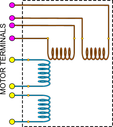
Bipolar motor
This configuration is the most simple. 4 wires are used to connect the motor to the controller. The coils are internally connected either in series or parallel. This is an example of a bipolar stepper motor:
The motor has 4 terminals. The two yellow terminals (the colors i use are NOT according to standards!!!) are for powering the horizontal coils, while the two purple terminals are for powering the vertical coils. The problem with this configuration is that, if someone wants to change the magnetic polarity, the only way to do this is by changing the current direction. This means that the driver circuit will have to be complicated, for example with a H-bridge.
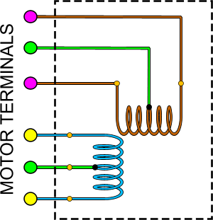
Unipolar motor
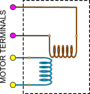
In a unipolar motor, a common wire is connected to the point where the two coils are connected together:
A unipolar motor with 5 terminals
With this common wire, the magnetic poles can now easily be changed. Suppose for example that we connect the common wire to the ground. By powering once the first end of the coil and once the other end, the magnetic poles are changed. This means that the circuit for a bi-directional motor application is very simply, usually with only two transistors per phase. A major drawback is that, each time, only half of the available coil windings are used. This is like the motor is driven with single-coil excitation. Therefore, the torque generated is always about half the torque that would have be generated if both coils were powered. In other words, unipolar motors needs double the space as a bipolar motor, to provide the same torque. The unipolar motor can be used as a bipolar motor, simply by leaving the common wire unconnected.
Unipolar motors may have 5 or 6 terminal wires. The drawing above demonstrates a unipolar motor with 6 wires. There are situations though, that the two common wires are internally connected. In this case, the motor will have 5 wire terminals.
8-lead stepper
This is the most flexible stepper motor in terms of connection modes. All coils have wire terminals for both sides:
This motor can be connected with any connection possible. It can be connected as a 5 or 6 leads unipolar, as bipolar with series windings, as bipolar with parallel windings, or as bipolar with single winding per phase for lower current applications.
Dear sir,
Thank you for gave the information about stepper motor works.
I understood the principle of working with the help of animation.
Regards,
G.Parthiban, Kalpakkam.
At 20 October 2015, 11:46:29 user Mike D wrote: [reply @ Mike D]
Awesome, thank you. I did find it just a bit slow for me but that is because I knew some of this before coming here.
That said it has given me a great deal of new knowledge and insight that will help me connect up my first stepper motor and have it actually work.
Thank you again.
Great tutorial! I suggest you slow the animations down, perhaps leaving a 3 second interval between steps. As it is now, it is visually difficult to keep up with each step of the sequence and study how the current flows through each winding.
Thanks for your efforts.
Dear Giorgios,
Fantastic explanation and didatics! I disassembled a disquette drive and found a very strange looking motor inside. Now I know it`s a stepper motor. Could you please inform with what software you designed the 2 demo videos?
I have a bunch of stepper motors that have failed. When installed in the machine they just vibrate back and forth. I know it is the motor because when I put in a new motor they machine works just fine.
Do you think there is anyway to repair these stepper motors?
It is a Hybrid .9 degree NEMA 23. Do you think a coil shorted or is it something to do with the magnetism? Or??
Thanks
Russ
At 25 January 2013, 0:46:08 user Bojar wrote: [reply @ Bojar]
Your explanation makes this so clear...Thanks!
At 1 January 2013, 10:27:48 user swamy wrote: [reply @ swamy]
u explanation is just awesome.thanq for giving valuable inf.
VERY GOOD PRESENTATION FOR BASIC CONCEPT FOR STEPPER DRIVE.
PLEASE GUIDE US FOR BIPOLAR STEPPER DRIVE & UNIPOLAR DRIVE.
IS BIPOLAR DRIVE WORK ON UNIPOLAR.
WHAT IS THE DIFFERENCE IN BIPOLAR & UNIPOLAR
YOUR GUIDE LINE IN THESE MATTER WILL BE HGIHLY APPRECIATED.
At 24 September 2012, 23:36:38 user truk wrote: [reply @ truk]
OK that animation mid-page on the right finally clicked in for how real steppers work and how you can get to smaller steps. All the beginner diagrams only show 4 poles and compass style rotors with giant 90 deg steps. that animation is fantastic, thanks so much!
At 19 September 2012, 14:10:43 user brijesh wrote: [reply @ brijesh]
@Vimee Bakori first disconnect completely the wires from the motor. You will need either 4 multimeters, or 4 LEDs or other source of light. Then , you must see between each of the 4 wires and the ground a pulse. The pulse must follow the pattern of a full or half step as explained in this article.
At 16 August 2012, 13:35:39 user John wrote: [reply @ John]
Good Day and Many Congrats for your presentation!
One question pls...
In a step motor with 4 wires (1=R, 2=S, 3=T AND 4=COMMON ),
how can measure by multimeter the voltage in order to understand if signal is correct?
i.e. I can measure sometimes 31V Only to one of three cables, or only to 2 of 3, or to all 3 cables...
How is the constraction of 4 wire motor with common ?
You definitely were born to be a teacher. What a great elementary style tutor in stepper motors. I actually understand how they work now. Something I thought I would never understand.
@Stefan
1. Depends on the stepper. For example, one stepper may have 5 ohms coils. Then, you will measure 5 ohms between the sides of the coil, and 2.5 ohms between one side and the middle wire.
2. You don't need to recognize them, they are bipolar motors. Only bipolars have 4 wires.
3. As i said in point 1, a 5 (or 6) wires motor has 2 coils. So, you must find one big and one small resistance between the coils. When you measure the resistance and you find the "big" resistance, then you are sure that you are holding the ends of the coils. Now be careful!!! If the motor has 5 wires, this means that the middle coils are internally connected! What this means is that you may find a big resistance between the ends of ONE coil, or between the ends of the 2 coils!!! That will trick you. No matter what, big resistance comes only from end-side of coils. Small resistance (which is half the big resistance) means that one wire is the middle.
Hi there,very good explaining about the stepp motors and how they work.I have 3 questions about them.
1.If I messure resistance on the coils,what I will get?
2.I have 2 stepp motors,they have 4 wires.And how can I recognize them?
3.The common pin how I can recognize it from the others,is there any resistance or something like that so I can recognize it?
Thank you
I really appreciate your presentations. I happen to be a experimental biologist student, and wanted to understand dc and stepper motors so i could understand what is to be believed the mechanism of bacterial flagella.
Your information is priceless.
Dont worry about your accent, should someone not like it they can look elsewhere for the knowledge they seek.
Thank you.
@Terje damn i saw your post in the forum and totally forgot to answer. I will answer in the forum asap.
http://pcbheaven.com/forum/index.php/topic,1159.0.html

 Home
Home
 Projects
 Experiments
 Circuits
 Theory
 BLOG
BLOG
 PIC Tutorials
 Time for Science

 Contact
 Forum
Forum
 RSS
RSS


 Reddit this

