How Brushless Motors Work (BLDC Motors) This motor could be characterized as the modern kind of DC motor. The letters BLDC means Brush-Less Direct Current. So, these motors have no brushes. If you do not know what the brushes are, then you should first read the article about How Brushed DC motors are made and how they operate. It is better to start learning from the simplest motors.
How are the Brushless DC (BDLC) motors made?
PC fans use BLDCs for their silent operation and reliability
The controller circuit for PC fans is so small, it can fir on the back side of the motor!
The brushless motor, unlike the DC brushed motor, has the permanent magnets glued on the rotor. It has usually 4 magnets around the perimeter. The stator of the motor is composed by the electromagnets, usually 4 of them, placed in a cross pattern with 90o angle between them. The major advantage of the brushless motors is that, due to the fact that the rotor carries only the permanent magnets, it needs of NO power at all. No connection needs to be done with the rotor, thus, no brush-commutator pair needs to be made! This is how the brushless motors took their name from. This feature gives the brushless motor great increament in reliability, as the brushes wear off very fast. Moreover, brushless motors are more silent and more efficient in terms of power consumption.
A brushless motor has yet another major difference from the brushed motors. In the theory of operation of the brushed DC motors with permanent magnets, i explain how the commutator is made and how the coils changes polarity during rotation. But brushless motors have no commutator nor brushes. Thus, there is actually no way of knowing where each time the rotor is.
Well actually they do know. There are several ways to find out where the rotor is. Sometimes they use rotary encoders along with their controllers and they know exactly the angle that the rotor is. Others use pairs of Hall sensors while most of them use just one Hall sensor. You can learn more information about the Hall sensor in this page. The Hall sensor is placed in an appropriate position. It can sense if in front of it is the North or the South pole. The Hall sensor will then transmit this signal to the controller of the motor. The controller will then switch on or off the appropriate coils needed in order to provide the torque. And that's the way it goes...
As you understand, this is a major drawback of brushless motors. They need of a controller circuitry to operate. Yet when reliability is required, this motor is the most suitable. The following video demonstrates exactly how a typical (and very popular type) of a brushless motor is made:
How the brushless motors work?
The trick of operation in BLDC motors is the Hall sensor that is attached to the stator. It faces the magnets perpendicularly and can distinguish if the North or South pole is in front of it. The following image shows this Hall senor. The photo is taken from a PC fan (yes, PC fans do have BLDCs!):
If you want to learn how the PC fans operate, follow this link. To better understand the operation of the Hall sensor in respect to the rotor position, i will show you an animation with only 2 magnetic poles and 2 coils. The magnetic poles are both South poles:
The Hall sensor is this little component under the right electromagnet. When it senses the South pole, it keeps the coils turned off. When the sensor senses no magnetic field (or could be also the South pole), then it turns on the coils. The coils have both the same magnetic polarity which is North. So they pull the opposite pole and torque is then created.
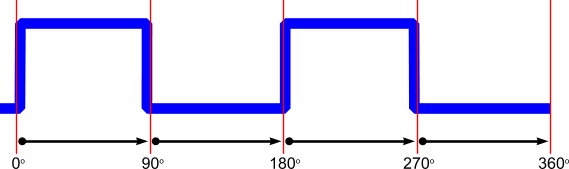
If you put a probe to the Hall sensor and watch the signal, then you will discover that during a full rotation of the rotor, the Hall sensor is two times HIGH and two times LOW. The waveform on oscilloscope would be like this one:
Yet another great advantage for the brushless motors. This very signal that is used to control the coils, can be used as is for measuring the speed of the motor! It can also be used to see if the motor is functional or not! Actually, this signal is exactly the one that comes out from the third wire from the PC fans that have 3 (or 4 wires)! These fans do not have any extra circuitry to measure the speed of the motor. They use the signal from the Hall sensor. Each revolution will generate 2 pulses. With a simple frequency measuring circuitry, someone can measure precisely the rpm of the motor.
A real brushless motor has 4 coils
I explained above the operation principle of a brushless motor with 2 coils and 2 permanent magnets. Yet, in real life, BLDCs have usually 4 coils and 4 magnets. Also, the Hall sensor is able not only to see if a magnetic field is in front of it, but also to distinguish if this is the North or the South pole. This is how a real BLDC motor looks like:
Around the perimeter of the rotor, there are 4 magnets in N-S-N-S patten. Also, there are 4 coils. The windings of the coils are not all of the same direction. 2 neighbor coils can never have the same magnetic polarity. The coils are connected in pairs, either each one with it's opposite coils, or there in two pairs or neighbor coils like shown on the above drawing.
The simplest operation cycle is, according to the pole that is in front of the Hall sensor, the controller will turn on or off the appropriate coil pair. The following animation demonstrates this cycle of operation:
And when the Hall sensor is between the two poles?
I had this question myself. What will happen if the rotor is stopped in a position where the Hall sensor is exactly between two different poles? Look for example the following drawing:
It may happen... Now the Hall sensor cannot sense exactly which pole is in front of it. Well, this is actually not a big deal... Suppose that the sensor senses the wrong pole and gives power to the wrong coils. What will happen? For a fraction of a millisecond the motor will try to rotate the wrong way. But a few degrees of rotation will bring the correct pole in front of the Hall sensor and it will immediately change the coils. Thus, the motor will then turn on the correct rotation.
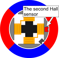
But what if the motor controls a critical load and this backwards rotation, even if it is under 5o must NOT occur? There is a solution for this, but it requires the use of another Hall sensor. The second sensor will be placed with 45o difference from the first one:
Now, even if the first Hall sensor cannot get a proper reading, the second Hall sensor can clearly distinguish the magnetic pole. The controller will accept as "correct reading" the one that comes from the sensor with the most intense signal.
The Sensorless BLDCs
Yet another variation of the brushless motors. Using a Hall sensor will result in an increase of the overall price of the motor. Moreover, there are situations that a sensor cannot be used, as for example in submersible pumps, or in applications where the wiring must be kept to minimum. In such applications, the sensorless BLDC can be used instead. The operation of such motor is based on the BEMF effect. The BEMF (Back Electro-Magnetic Force) is inducted by the movement of a permanent magnet in front of a stator coil.
There are two problems that must be solved for the proper operation of the motor. First of all, the rotation direction. As no sensor is used, the controller cannot know where the rotor is stopped at any time. Thus, the rotation direction that the motor will start is -at least for the first degrees of rotation- coin toss. The other problem is the zero detection. The controller does not know when to change the polarity of the coils, as there is no sensor to sense when the permanent magnet pole crosses a specific point.
There are special designed controller chips to solve these problems. The chips will use the characteristics of the BEMF and the voltage generated on the coils from the BEMF effect. For example, the current produced on a coil due to BEMF will change its polarity, if the rotation of the permanent magnet is changed. Also, the amplitude of the produced waveform is proportional to the speed of the rotors, and the phase of the waveform depends on the position of the permanent magnet in respect to the coil. Yet, this is not the proper article to discuss about sensorless BLDCs in details.
Sir,
I want to brake these BLDC motors. how can it be made possible. i am using a 250W bldc hub type motor. It is a three phase motor, i use an external controller. Please tell me how i could i apply braking (electrical braking) for this motor.
Thank you.
At 31 March 2015, 11:36:09 user vamsi wrote: [reply @ vamsi]
Great explanation and great presentation, thank you very much!!! by the way, I want to ask you which software do you use for your 2D drawings and animations??
because it looks great the way you made it!! thanks again!
At 17 October 2014, 19:05:28 user Hank wrote: [reply @ Hank]
@ali Try this link http://www.emic-bg.org/files/Electric_Motors___Drives.pdf
At 17 October 2014, 19:00:14 user Hank wrote: [reply @ Hank]
@vineetha Torque is proportional to current. If you can control the current through the motor, torque will be controlled. Likewise, voltage, and also back emf, will be proportional to speed. Therefore, with a fixed voltage power supply, the motor speed will increase, and increase back emf, thus reducing current until equilibrium is reached when the motor speed no longer accelerates. At this point, its torque output equals its load.
At 17 October 2014, 18:49:10 user Hank wrote: [reply @ Hank]
@Dom Yes. You may have to remove the hall effect sensor but before you do this, determine which pin is its output, then apply a square wave to the pin that the hall effect sensor would normally pulse on and off, it should fool the circuitry into thinking the rotor is present and create a rotating magnetic field. Another possibility, before removing the hall effect sensor is to fashion a small piece of iron that can jumper the magnetic circuit from one of the electromagnets to the hall effect sensor. If the polarity of the magnet is correct, it should oscillate rapidly, probably faster than the motor normally runs creating a rotating field. If the wrong polarity magnet is chosen, it will not oscillate. Try other electromagnet pole faces until it oscillates.
At 8 October 2014, 17:30:18 user Dom wrote: [reply @ Dom]
If I wanted to generate an electromagnetic field with no moving parts can I use a brushless PC fan motor to do so?
I removed the fan and magnet applied power and for a show burst my EMF detector did detect the filed but then it stopped. I noticed that f I pulsed the power I cold sustain the EMF. I am assuming that only one coil (maybe two) are powered up and creating the EMF. Since the magnet is missing the hall effect sensor has no way of triggering so it shuts down.
Is there a way to get the coils to power up in a continuous circular rotation without using the magnets within the fan blades?
At 6 October 2014, 20:32:09 user Hank wrote: [reply @ Hank]
@AMIR No, no starter is needed because regardless of where the rotor stops, the hall effect sensor will sense the rotor's position and energise the appropriate coils to repel or attract the adjacent rotor magnets to create torque in the rotor to make it turn in the correct direction.
At 5 September 2014, 10:39:49 user AMIR wrote: [reply @ AMIR]
thank you for this information but ow this motor start to rotate? Does not need the motor starter coil? Especially in larger motor?
In "A real brushless motor has 4 coils" part, you said "2 neighbor coils can never have the same magnetic polarity". But for each 2 neighbor coils, I find they have same magnetic polarity by Lenz's law.
The information which u have given was excellent.i want some information about the "instantaneous torque control of small inductances brushless dc motor".please help me.
At 24 February 2014, 13:14:02 user ali wrote: [reply @ ali]
Hi
I want to have some document about brushless motor and design this motor can you help me?
if you have some document please email for me
thanks
you have done great work for every new batches students to build a simple dc machine as a project or another work to know how to work.thanking you for this work
try this one
http://ca.mouser.com/ProductDetail/STMicroelectronics/L6234/?qs=sGAEpiMZZMvHdo5hUx%252bJYgwT2LFgUEMo
I have it but so far I haven't had the time to use it.
and I'd recommend this one for beginners
http://ca.mouser.com/ProductDetail/STMicroelectronics/STEVAL-IFN004V1/?qs=sGAEpiMZZMvx4iVJH4BFx6IrCyRngqWa
my first uC chip was the stm8s, they have all datasheets and the peripheral libraries to get you started and a lot of example codes for all their products.
I havn't used the STEVAL-IFN004V1 but from the looks of it I'd assumed it comes already programmed so all you have to do is hook up your motor
you can also write your own code to the board using the SWIM pins
which you'll require the 511-ST-LINK/V2-ISOL debugger
Dear Sir,
Myself Rajakumar D.G. A faculty of Mechanical Engineering wants to know the importance Brushless DC Motors in the regular fan (at present it consumes 60-70W)which normally used in domestics.
I had a plan to design BLDC for small scale applications.
Let us know the feedback at your end.
Thanks & Regards
I have to assignment to design the sensorless BLDC submersible pump motor drive for farmers. Can anyone help to do same?
I am good in embedded design but I don't know how to measure this BEMF, which I think need to measure in sensorless BLDC motor.
Anyone know for any chip or IC direct available to measure BEMF and generate this logic to drive the MOSFET or IGBT?
My motor has three wires output U,V,W and in rotor has six magnets. I know only this information.
@Launcelot It definitely reads the BEMF. I haven't write much about BEMF BLDC motors although i planed to do, but time is a luxury that i do not have these days. You can learn a lot from BLDC application notes though and you can follow the circuits from microchip application notes (google them)
Hi,
Mr.Lazaridis
excellent excellent!!
Thanks a lot for the reply and for clarifying the phases for me
i have used oscilloscopes in schools but never really bothered thinking about the importance of it, now thanks to you again i will definitely be buying one. come to think of it after mentioning the oscilloscope in the reply you sent i quite did some researches on it and i realize that it will be helpful.
i have finally found the driver that i will be using.
another confusing question.
i have disassembled my BLDC checked.. double checked .. doesn't seem to
have any hall sensors ?? just about 6 black bolts screwed into the moving(rotating)drum which doesn't look anything like hall sensors ?
if a BLDC had hall sensors, would it have extra connecting pins ?
because the driver i have gotten for the BLDC has inputs for hall sensors but my Motor doesn't am assuming it has BEMF
ohh and also, (c) common should also go to ground right ?
@Launcelot! Hello! This is definitely a BLDC. I may assume it is a 12 pole 3 phase motor (each phase has 4 coils in cross-pattern). U-V-W are the ends of the phases and C the common (most likely).
To find out the pins, do a test. Apply some 1-2V at one phase (say U) and ground to PG. Then probe with the oscilloscope the other output. Revolve the motor by hand. It could be a feedback from the BEMF or hall sensor.
For the speed, i can't tell, but 3700 i think is a low speed for this motor ;)
HEY!! Giorgos Lazaridis, thanks website!!
I really need some advice in brushless Motor
I am making simple project this summer based on this BLDC motor I found
in a DVD player. I'd be really thankful if you can help me
since I have nothing do to this summer, just felt like locking myself up in my basement and building something fun.
this is my first time learning about brushless motors
all the researches I have done talks about 3phase motors, but this motor I have might be a three phase motor, am not sure.
it has 12 Stator with coils around. with four coil wires labeled( C W V and U) coming from the coils and soldered on to the board. at the end of the board it has five pin outs labeled UV W 2 5 and PG. this isn't suppose to make sense for anybody but am wondering is the motor 5 phase , 3 phase or 4 phase i don't know ?? assuming that BLDC motors have no Voltage pin nor a Ground pin because they only rely on the PWM applied to the phase ? or they might have but again i am clueless.
what makes a motor 3 phase or 5 phase ?? mine has 5 pin connections
this is an image of the exact motor I have
is this in fact a BLDC motor ? and I am assuming it is a 5 phase ?
and if it's a 3 phase what are the extra 2 pins ?
i intend to operate this with an ARM7 uC If i could figure out the phases it has i can decide on which BLDC driver would best suit my project.
sorry for the long comment
i really need to get things started.
any information would be helping.
(OPTIONAL comment) : I am assuming you're an expert so judging from the
image what is the max RPM do you think this BLDC can output ? 3700RPM perhaps ?
@Wesley this can be controlled by the microchip controller
At 27 February 2013, 18:08:33 user Wesley wrote: [reply @ Wesley]
In the 4 pole motor animation, you say that another sensor can be placed at 45 degrees as shown in the drawing. This is supposed to allow for proper starting of the motor, but won't the 45 degree sensor turn on the coil too early?
I am looking forward for the BLDC electrical Equilant circuit diagram. and how much the total energy losses including coper and iron losses
At 16 June 2012, 0:06:13 user Hank wrote: [reply @ Hank]
I would like to comment on why most BLDCs of this type do not need a second hall effect sensor to find their position when first starting from a stop. The curved ends of the stator electromagnets do not have the same gap from the electromagnet core to the rotor permenent magnets at the leading and trailing edges. One end has a smaller gap, the opposite end has a larger gap to the PMs. The rotor will tend to stop with the smaller end gap nearer the center of the permenent magnet. Therefore the motor will be unlikely to stop with the hall sensor between two rotor magnets.
If a PC fan without power applied is turned slowly with a finger, one can feel the permenent magnets' attraction through the smaller gap to the stator iron cores decrease as the rotor is turned until suddenly no torque from your finger is required and the fan suddenly snaps forward to the next position where the permenent magnet is again centered over the next electromagnet's smaller gap. Hope this helps as well.
thanks a lot for this info.this is very usefull information. actually i'm electrical engineering student.i'm working very hard on my final project about the comparative study of vector control of BLDC and induction motor. can you help me please? this project based on simulation of MATLAB. thanks a lot!
Very informative about what is BLDC motors. I would like to know whether there is any simple way out so that one can simply run a spindle motor of a hard disk.
@fiddle the problem with PC fans is that the hall sensor is active component and needs polarization (power) to operate, so you need to connect the fan to power first. If the sensor has external power (like the CD tray motor - http://www.pcbheaven.com/exppages/Reverse-Engineering_DVD_Head_Linear_Guide) then you will get output
At 19 February 2012, 23:00:39 user fiddle wrote: [reply @ fiddle]
Is it possible to get signals from hall sensors if you just rotate the rotor (motor is not power supplied)?
@szilviki i have never met one with this configuration, and i do not believe that exists one. i do not see any particular reason why someone would run a fan with stepper motor. after all, steppers do not rotate fast.
You say: "Yet, in real life, BLDCs have usually 4 coils and 4 magnets." However, the image you show for the non-real-life magnet is the same as the image you show for the "real life" magnet. Both have two magnets - neither has four.
At 30 September 2011, 6:13:57 user somu wrote: [reply @ somu]
can u explain in detail abt movement of rotor?
At 22 September 2011, 21:17:13 user VO-TAN wrote: [reply @ VO-TAN]
Hi,
I do think that the coils were damaged, I do not smell bad and the heat.
At the beginnig, as the model was new I do not force on the friction of my hand to stop the motor and now, after the crash, I force with a friction of my hand to stop the motor but the problem could exist even at the beginning. I do not know
In all cases, thanks a lot for your help.
I am waiting for the new propellers already ordered, I will try and advise you
Bye
@VO-TAN [As a matter of fact, it would be rather strange if just one motor had this problem. ]
I mean that the problem that you describe is very strange. I would be surprised if even one motor had this problem. In order for a motor to have a decreased torque, the coils have to be damaged. But if the coils were damaged, you would be able to tell from the smell and the heat. And also, usually if something goes bad with the motor coils, the motor stops running completely.
At 22 September 2011, 20:59:08 user VO-TAN wrote: [reply @ VO-TAN]
Hi,
It is highly unlikely that all 4 motors have this problem.
[I agree with you]
As a matter of fact, it would be rather strange if just one motor had this problem.
[I do not understand what you mean? You would like to say:
It would be rather NOT strange if just one motor had this problem, wouldn't it?]
So, relax and check your electronics for other problems instead.
[Thanks]
BTW. i suppose these are 2-phase motors right?
[I really do not know what it means?)] :)
Best regards
@VO-TAN it is highly unlikely that all 4 motors have this problem. As a matter of fact, it would be rather strange if just one motor had this problem. So, relax and check your electronics for other problems instead. (BTW. i suppose these are 2-phase motors right?)
At 22 September 2011, 20:41:33 user VO-TAN wrote: [reply @ VO-TAN]
Hi,
This happens to all 4 motors of my quadrotor (plus or minus). I am happy if the coils are not damaged as per you. I do not think that the shaft is damaged or anything else mechanical. The motors have an external controller and 3 wires comes out of the motor.
Best regards
@VO-TAN this happens to all 4 motors of your quadrotor? It is more likely that the shaft is damaged or something else mechanical happened, rather than the coils are damaged. The motors have a built-in controller or you have external controller? And how many wires comes out of the motor?
At 22 September 2011, 13:02:08 user VO-TAN wrote: [reply @ VO-TAN]
Hi,
Thanks for your rapid answer.
My detailed problem is I crashed my Quadcopter (multirotors model)and during a few minutes, the brushless motors were blocked in rotation but the voltage still supplied the motors (11.1 volt - max controler 10 A).
After repair, the motors seem turn normally but I do not know if something is damaged or not (without external sign)?
I feel that I can lower down the motor speed (without propeller) by friction of hand, more easier than original configuration. Feeling only?
Thanks in advance to advise the health of my system
@VO-TAN 10A is not a small motor. Depends on the controller. If the motor is sensorless, then the controller will continue to send current to coils and this could heat up the motor.
At 22 September 2011, 11:57:21 user VO-TAN wrote: [reply @ VO-TAN]
Hi,
Firstly, thanks for this interesting article.
Secondly, what's happened if I block the rotation of the brushless motor by hand (small motor up to 10 A)
Thanks
thank you very much! I was more interested about the Sensorless BLDCs, especially how the vector control works. Thank you again for sharing your knowledge with the world :)
At 16 January 2011, 12:42:41 user Nicole wrote: [reply @ Nicole]
Dear,
Its really good document to start with, Thanks for your effort.
I am trying to design a bldc motor (infact conversion of existing dc motors?), and running my MTB using this BLDC, where and howto start with is a big question in front me, can you please guide me?
few criteria's which bogging my head was low wattage, human assisted pedalling, 19kmph and different road positions, like few hundred meters, cycle has climb, 25Ah 12VDc SLA,
I am not sure it the earth's magnetic field can cause such an interfere to the motor. And if it does, i don't think that choosing a brushless or a brushed can change this. That is a very nice thinking you got though, and i wonder if an experiment could be made to test it. How come and you noticed that there is a difference in rotation - and this made you assume that the earth's field could affect the motor- ?
I am using a motorized precision gyroscope (from www.gyroscope.com) to demonstrate the behavior of a gyro-compass, http://web.mac.com/mikallen/iWeb/Gyro-Compass/Gyro.html. I replaced the stock DC motor(brushed) with a brushless motor to reduce or eliminate the tendency of the brushed DC motor's static magnetic field to make it behave as a magnetic compass. I'm thinking that when spinning the brushless motor will exhibit a rapidly rotating magnetic field and thus it's position will not be influenced by the earth's magnetic field. Please share your thoughts.
-If you find more info about these fans please do send me. I am curious to see.
-If you see this link: http://pcbheaven.com/wikipages/How_PC_Fans_Work
You will understand that the coils of the PC fan are not connected directly to the power lines, instead goes through mosfets or transistors. That is why you need to rip off the controller.
- P=138.8[KJ]/10[Sec] = 13.8 K-Watts, NOT K-Watts/time. The Kilo-Joule can be directly converted into Watt-hour: 1KJ = 0.27 WHour, so it is about 37.4 WHours
A 13.8 KWatts motor is not unrealistic nor huge. A CNC for example carries a 15KW main spindle motor (like this one: http://pcbheaven.com/projectpages/Men_Of_War_Game_Console/?p=4&topic=worklog )
A few remarks,
First batch: Please see the wikipedia link I referred to. Yes I am positive. It was shown to me by an extremely experienced electrician at his car electricity garage. They are on the market for quite a while now.
But an although an extensive web search I was not able to bring you an example. (Perhaps they have some special name, and more important, it seems as you contend, they are NOT brushless).
2nd wave: Why do you need to access anything on the PC fan's internals. Isn't connecting to the wires and turning the fan enough?
What if a second fan pushed the first fan at its current speed.
Did you mean millivolts or volts?
Thanks and sorry if I'm asking too much. (My first grade teacher Mrs Siterer wrote that on my report card!
Oh, and to answer the question not asked, but inferred from your answers:
A generator capable of 13.8 kW/sec = ~ 50 MW/hr!! Or am I making a mistake? Isn't that a generator for a small building?
Is that's what is needed to stop a 1 ton car at 60 km/h within 10 seconds?
Actually I did read of the shocking fact that a typical short 4 mile car ride can take more energy than we use at home for the whole day, including lights, refridgerator, microwave, pc and air conditioning!
Regarding the first series of question:
>a PC Fans do have permanent magnets: http://pcbheaven.com/wikipages/How_PC_Fans_Work. In that case, you must have DC coils on the rotor, and that would require brushes to power them. There h\goes the "brushless" term. Frankly, i do not know any other way. But i sure do not know everything. Are you sure that this car starter was BLDC without PMs? That is really weird and i would like to know more about this.
>b. As i said, you may have DC wounds on the rotor or stator (excitation coils). But that would require power for the rotor (either for the excitation coils or the armature), which means that it should have brushes. That would not be a brushless. Again, i sure do not know everything and i may be mistaken.
>c Sorry, i did not understand your question. A generator will "consume" mechanical power and convert it into electrical to be stored. The amount of energy provided will be h x MechPower, where h is the efficiency. You don't provide any power to the generator at all, unless it has excitation coils (as usual) and you provide a small DC voltage, not more. If i did not answer it again, please rephrase because i did not understand it.
------------------------------
Regarding the 2nd wave of wquestions:
a> It is not 100% sure that it work as a dynamo, due to the built-in controller with the mosfets. I tested one right now and provided only a few volts. The efficiency sucked. BLDCs usually can provide power. PC Fans are not just a BLDC.
b> There are no standard values, but usually have power of a couple of watts (1 to 5) and rotate from 800 to 2500 rpm. But there are other fans that do not comply with these numbers.
c> The faster you rotate it, the more voltage you get. That is a rule. The only problem is the mechanical strength. If you turn it much above the nominal sped, it will probably break apart. But again, not a PC fan. You must remove the circuitry form the fan to have access to the coils.
I re-read your article. So I have another question, or rather series of questions (I'll still be happy to hear answers for the first ones too):
a. If the PC fan is a BLDC with PM's it can be used as a generator (dynamo), no?
b. How much power does a fan like that typically take, how fast does it typically turn, and what is the power equivalent in typical voltage used and amperes?
c. If it can be used as a generator (dynamo) how fast do I need to turn it, to get a significant amount of power (say 1 volt at 1 ampere), and how fast to get back the power typically used to run it?
Thanks Kammenos for your answer.
>a. ...reluctance motor
That uses a feromagnetic rotor (i.e. non magnetised metal that is pulled or pushed by a magnet). I rather am talking about a BLDC with no PMs. AFAIK and understand, the tiny fan motors for a PC have no PMs in them at all, is that correct? Even if they do, I have seen new BLDC car starter motors with no PMs whatsoever...
>b. ...generator without pm's
If an AC alternator can (http://en.wikipedia.org/wiki/Alternator#Brushless_alternators) why can't a dynamo?
>c. use the numbers...
So 16.2 kW over 10 seconds to stop the 1 ton truck at 60 kmH.
(retarder "motor" efficiency h=0.85, output power 13.8).
But my question was about a generator being used as the retarder.
In this case, if I want to get regenerative braking I have to "transfer" 13.8 kW * 10 sec) into stored electric power. My question was pertaining to a positive answer to b - and then asking: How much power do I need to input (assuming zero for a one PM one EM rotor/stator set) in order to catch all (ok, most of) that kinetic work and turn it into battery stored electricity?
a. I think that you mean Reluctance motor. Check this out http://en.wikipedia.org/wiki/Reluctance_motor
b. No, they can't. A rotating magnetic field cannot be generated without permanent magnets or DC current in wounds on the rotor (Like the normal generators)
c. Regenerative braking does indeed slow down a rotating shaft. The (electric or other) power provided is less than the breaking power achieved, acording to the efficiency of the breaking device (could be a generator). Now, the amount of breaking power, has only to do with the breaking device characteristics. You can calculate the kinetic energy of a moving vehicle:
K[Joules] =1/2 Mass [kilograms] x Speed^2 [Meters/Second]
So, the energy of a 1 ton car running with 60 Km/hour is:
K=1000 x 16.6666 / 2 = 138.8 K-Joules
and
P[Watts]=E[Joules]/t[Seconds]
To stop this car in 10 seconds, you need to break constantly with:
P=138.8/10 = 13.8 K-Watts
And if your generator has typical h=0.85, then it must be able to provide 13.8/0.85 = 16.2 Kilowatts, which is fairly enough.
Use the above to calculate the motor needed to make a retarder for a 30 tons truck running with 80 Km/Hour!
a. Is there a special name for a BLDC motor with only electromagnets - and no PMs (permanent magnets), or is it simply a "BLDC motor without PMs"?
b. Can a simple BLDC with only electromagnets (no PMs) be used as as a "dynamo" generator. If so is it as efficient as a PM dynamo, and how much energy would be needed to run it, and what would the expected ratio of output vs input be (I'm not asking for exact numbers, just a rough idea)
c. Perhaps not for this thread... but on the same idea: Would regenerative braking slow down a rotating shaft in the same amount (speed/torque/power) a retarder (like the telma which dissipates the energy into heat) would?
At 28 October 2010, 3:56:05 user rohan wrote: [reply @ rohan]
The equation is Ael = Amech x P/2. To solve for A mechanical, it would be:
Amech = 2 x Ael / P (P=number of poles). Do not forget the 2. Please let me know when you test the motor, if it worked with the angles that i gave you. I am most interested.
Kammenos in your last post you claim that the right equation is Ael = Amech x P/2 and i belive that the equations is mechanical angle=electrical angle*pair of poles. So we write the opposite equation, but now that i think again this, i think that the correct is mechanical angle=electrical angle/pair of poles! So i was wrong in first palce! but we agree at the numbers of poles. Yes, i think so that you can define as \'first\' whatever coil you want.
i think that is: mechanical angle=electrical angle*pair of poles, so i think 6 magnet = 3 pair of poles , because the magnets are rotating in bldc as the poles are rotating in sychronous ac motors. So i believe, that correct angle of sensors is: 180 angles( 3*60 ) and 360 angles(3*120) . But Where is the start point of angle? at first coil maybe ? am not sure
At 4 October 2010, 16:47:08 user Lyle wrote: [reply @ Lyle]
I also got from another source:
120/polepairs = X
X times 1 = the 60 electrical degrees
or
X times 2 = the 120 electrical degrees
So....
120/6 = 20x1= 20(for 60 degree hall placement)
120/6 = 20x2 = 40(for 120 degree hall placement)
So, first of all, what is electrical degrees. It is defined as the angle required for the rotating field to move from one pole to the next pole of the same polarity. You need to know the number of poles that your motor has. The poles are the number of magnetic poles that are generated from the magnetic field. For example, a 2-poles motor has one North and one South pole generated.
If i take a wild guess, i would say that your motor has 6 poles. That may NOT be accurate though. You need to confirm the info.
The equation for the electrical degrees in comparison to the mechanical is: Ael = Amech x P/2, where Ael is the electrical angle, Amech the mechanical angle and P the number of poles. If your motor has indeed 6 poles, then 60 electrical degrees is 20 mechanical, and 120 electrical is 40. In other words, your senror should be placed one between the first and second coil (60 el), and the other directly in front of the second coil (120 el).
I am NOT an expert to AC motors, actually i would say that i am rather a beginner. The info i gave you comes form a book (Stephen J. Chapman) about DC and AC machines, which i am reading these days for other purposes. I hope that i have not done any mistake in the calculations, and that i helped you.
At 3 October 2010, 18:04:22 user Lylr wrote: [reply @ Lylr]
3 phases ....
At 3 October 2010, 18:02:22 user Lyle wrote: [reply @ Lyle]
Motors will produce electricity if you rotate their shaft, so yes, there is a device as you described. But i cannot understand your second point. A generator will convert mechanical to electrical and a motor electrical to mechanical. The device you described what is it exactly? Converts electrical to both mechanical and electrical? What for?
Is there any equipment works like motor and generator at a time.
If i give electric energy as a input(motor) and i want mechanical energy and electric energy as output(generator).
The software i use is the autodesk inventor. I do not have a copy myself, but i can freely use it in my work afternoons. It is not proper for the reason that i use it, as it is used mainly to draw mechanical parts. You should better look for a 3d modeling software such as the 3d studio max or any similar. The reason that i use the inventor, is that it is the only software that i have access to.
I am very interested in the animations or simulation software you used for the lesson on brush less motors. I am an industrial electronics instructor at a community college.From what I saw in your presentations I feel that software could be a huge asset to my classroom instruction. Can you tell me where you got it from.
At 27 July 2010, 3:11:28 user Prem wrote: [reply @ Prem]
Dear Moonis,
I think you need to get your basics right. The electrons on the magnets are magnetized according to the Quantum Mechanics theory and the inertia of the electrostatic motion which is causing the magnets to move is complimentary to the loop force acting on the single neutron present adjacent to the electron. So the two forces according to what is published in this article is perfectly correct.
Regarding the following statement copied from the article above...
\"The major advantage of the brushless motors is that, due to the fact that the rotor carries only the 4 electromagnets, it needs of NO power at all.\"
in a BLDC motor... I thought the rotor carries the permanent magnets :s..

 Home
Home
 Projects
 Experiments
 Circuits
 Theory
 BLOG
BLOG
 PIC Tutorials
 Time for Science


 Contact
 Forum
Forum
 RSS
RSS


 Reddit this

