
|
 Home Home
 Projects Projects
 Experiments Experiments
 Circuits Circuits
 Theory Theory
 BLOG BLOG
 PIC Tutorials PIC Tutorials
 Time for Science Time for Science
|
| ||
|
28 March 2010 Author: Giorgos Lazaridis The Hall SensorHistory The invention of the Hall phenomenon took place in the year 1879 in the Johns Hopkins University in Baltimore. An American scientist named Edwin Herbert Hall, while working for his doctoral degree, he discovered that, if current is flowing through an electrical conductor, and this conductor is placed perpendicular to a magnetic field, then a voltage is developed on this conductor on a right angle to the currents' path. This effect is called the "Hall effect", and the voltage developed is called "Hall voltage". The Hall voltage is measured in micro-volts. This invention was firstly used for making sensor to measure the DC current, or the intensity of static magnetic fields in laboratories, as the amplifiers to measure this voltage were big and expensive. The Hall effect sensors was widely used after the silicon semiconductors became popular, and an implementation of a sensor along with an amplifier in a closed package was possible (1960's). The Hall effect Suppose that we have a thin parallelogram conductive material connected to a current source. The current will flow within this material in an -almost- straight line. If perpendicular to this material a magnetic field is introduced, then on the edges perpendicular to the currents' path, the Hall Voltage will appear: 
When the magnetic field is introduced to the conductive material, the carriers (electrons or holes depending on the material) will be affected by the Lorenz force. Their path will be slightly curved. The carriers will be forced to gather in one side of the material, while on the other side of the material will gather the same number of opposite charged materials. This gathering of charges on both sides will generate a slight potential difference, the Hall voltage. Inside the Hall switch The simplest Hall sensor, has inside the Hall element and a differential amplifier. This amplifier must have some special characteristics. The Hall element may produce Hall voltages down to 20 microvolts. Therefore, the amplifier must have very low noise, high input impedance and high gain in order to detect and amplify this micro voltage. The output of the amplifier is usually driven through a Schmitt trigger and the sensor acts as a switch sensitive to magnetism. The Hall voltage (VH) is proportional to the current across the Hall element (I) and the density of the magnetic flux (B). To make the Hall voltage proportional to the density of the magnetic flux, the current must be kept constant. Therefore, usually Hall sensors have also a built in current regulator. The chip integrates also temperature compensation. A typical Hall sensor diagram is as shown bellow: 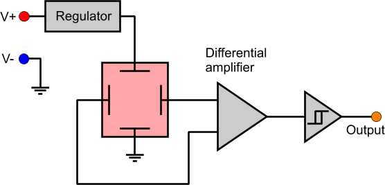
An analog Hall sensor Analog Hall sensors can measure the density of magnetic flux, and represent it with an output voltage difference. The internal diagram is similar to the Hall switch, instead of that an analog sensor, does not have a Schmitt trigger to drive the output. Instead, a transistor usually buffers the output and the output voltage is linear and proportional to the magnetic flux density: 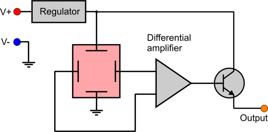
According to the magnetic polarity of the sensed field, the output of the amplifier can be either positive or negative. This would require of course double power supply with positive and negative voltages. To avoid this, many sensors have a DC offset to the amplifier. Thus, when the magnetic field is absent, the output of the sensor will not be 0, instead this offset will appear. A positive magnetic field will increase the output above this offset, while a negative magnetic field will decrease the output below this offset. The highest and lowest voltages have to do with the saturation points of the amplifier. The Hall element does not saturate itself, therefore it cannot be damaged from high density magnetic flux. The output characteristic is similar to the following: 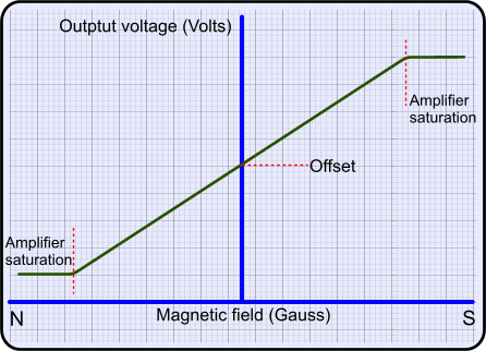
Applications  A Hall sensor package. It also has the amplifier built in.  A current measuring sensor using the Hall effect. The wire needs only to go though the hall of the sensor. The magnetic field generated by the flowing current will be measured by the Hall sensor  A Hall sensor for controlling the EFI of a motorcycle's engine. The hall effect has been applied to numerous applications. Using hall sensors, contactless current flow meters have been made. The current flow within a wire generates a magnetic field around it. The hall sensor is wrapped onto the cable and measures the magnetism. The intensity of the field is proportional to the current flow, while the Hall voltage is proportional to the intensity of the field. The great advantage is that the cable does not even need to be stripped! Also, it can be used to measure the intensity of magnetic fields for measuring applications. Further more, the Hall sensors can distinguish the polarity of the magnetic field. Hall sensors are also used extensively in the car industry. The solid construction and the lack of moving parts makes the hall sensor ideal to work in harsh environments and under heavy vibrations. The Hall sensors are used to find the position of the crankshaft, just like it used to be done with the distributor. The electronic fuel ignition systems needs to know when the crankshaft is in this very position, so that they calculate and ignite the spark plugs accordingly. Another application is found on the anti-block system of the cars. The sensor will sense if the magnetic field from the wheel is stopped and it will send a pulse to the controller to release part of the pressure on the break piston. Also it is used for measuring a vehicle's (usually bicycle) speed. A permanent magnet is attached to the perimeter of the wheel. Opposite this position, on the fork, the Hall sensor is positioned. It will sense a pulse every time the magnet pases in front of the sensor, once per wheel revolution. The controller will calculate the speed of the vehicle by knowing the wheel diameter. The Hall sensors are also used for synchronization in brushless motors. Their capability to switch on and off many times a second, makes them possible to be used for high speed BLDCs. The Hall sensor are used to distinguish which pole of the rotor permanent magnet is in which position, and turn on or off the appropriate coils accordingly. They are also used to measure the speed of these motors. Many applications in automation uses also Hall sensors. Pneumatic systems use them to find if a cylinder is extended or retracted. The piston of the cylinder carries a permanent magnet. A Hall sensor is positioned outside the cylinder. When the magnet is in front of the Hall sensor, it transmits a signal to the controller. Comments
|
|
 Contact Contact
 Forum
Projects
Experiments
Circuits
Theory
BLOG
PIC Tutorials
Time for Science Forum
Projects
Experiments
Circuits
Theory
BLOG
PIC Tutorials
Time for Science
 RSS RSS
Site design: Giorgos Lazaridis © Copyright 2008 Please read the Terms of services and the Privacy policy |


 Reddit this

