555 Tips and tricks
How to achieve duty cycle less than 50%
As shown above, the duty cycle from a 555 connected as an astable multivibrator is calculated from the following formula:
D =
R1 + R2
R1 + 2 x R2
Even if R1=0, the duty cycle cannot be lower than 50%.
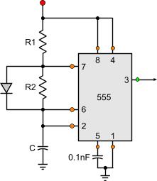
To achieve duty cycle less than 50%, a diode should be connected in parallel with R2:
During charging time of the capacitor, R2 will not be taken into account as the current will pass through the bypass diode. During discharge time on the other hand, the current will pass through R2.
With this trick, a duty cycle of about 0 to 100% can be achieved. Of course absolute 0 and 100 can never be achieved with a 555, but the real duty cycle shall be very close to those numbers.
Hi George, i need an opposite circuit with 555 timer. I want to give a positive pulse and after 0-2 seconds the output to be positive. I want to adjust 0-2 seconds. It is not called nomostable ,do you have any circuit ,do you know how its called?
@IBYISHAKA Marie Merci You can consider them as being the same. SE555 was the metal package and NE555 is the plastic dip package. They were the original chips, and then others came out from other companies with different letters (like LM555 from national semiconductors)
Sir,i would like ask if 555 timer works the same as NE555. and if they're not i would like to have much explanations about NE555. it's urgent!!
At 18 January 2012, 22:17:44 user Tom G wrote: [reply @ Tom G]
Thank you for your effort, very clear, excellent.
i need an escalating oscillator, i thought i should connect two 555's but i dont see how, in other words i need a pwm that has a automated escalating 'RC network',
any ideas?
Thanxs, Sir, for the genuine information which is precise, this is among the best sites i've visited, will always keep up to ur posts..........
At 25 June 2011, 6:22:19 user Fung wrote: [reply @ Fung]
TS555 or 7555 is the CMOS version of 555 timer, after viewing the datasheet of TS555 in ST (the only manufacturer of this part), its minimum supply voltage is 2V.
But I found some circuits which use these CMOS timers, but the supply voltage is 1.5V only, would it be unable to operate?
@Fung smoothing capacitors are always important if the power supply is not smooth, no matter what.
At 14 June 2011, 13:33:43 user Fung wrote: [reply @ Fung]
This is because I have a circuit using 556 timer (but not designed by me), 2 astables, but 1 extra resistor is found in one of them. I found that it is connected in parallel with C1 but in series with R1 and R2.
Use this connecting method gives a special effect on both outputs.
Are smoothing capacitors (that one which connects directly to the power supply and 0V rail) not allowed in 555 timer circuits?
@Fung i do not really know when it discontinued.
If you connect a resistor parallel to the C (as you describe it), it will change the charge time of the capacitor. This resistor must have a large value, otherwise the capacitor will never reach the proper value to trigger the internal lower comparator. Actually, i do not find any reason to connect such a resistor to the circuit. I would never do it.
At 13 June 2011, 15:29:54 user Fung wrote: [reply @ Fung]
When did the 558 quad timer discountinue?
Also, when a resistor is added between the "R2" and "C" and it is connected to 0V, what effects will the timer give out?
Fantastic clear and concise tutorial on 555 basics. Thanks for your efforts, very much appreciated!
At 17 February 2011, 15:18:30 user jack wrote: [reply @ jack]
no. i already set up the timer 50% duty cycle...i have a project with using the sensor..if the sensor give the input the duty cycle timer back to the origin..example i set up the timer 1 minute, if have the input from signal the timer set again 1 minute and so on
jack, i did not really understand your question. You want to make the duty cycle 0%? Check out this circuit:
http://pcbheaven.com/circuitpages/High_Frequency_PWM_Fan_Controller
At 17 February 2011, 5:41:02 user jack wrote: [reply @ jack]
i have a question..
how to reset the duty cycle back to start when the 555 timer is running..
there is no most correct. it only has to do with the frequency that you want
At 27 January 2011, 8:25:15 user Fung wrote: [reply @ Fung]
For the value of R2 of the 555 internal schematic, some datasheets state that it is 830R, while the others state that it is 330R. Actually, which one is the most correct?
how to calculated ranges of capacitance using a NE555 astable climb .. if you want the pattern but I'm sending you please answered months
Écouter
Lire phonétiquement
Dictionnaire - Afficher le dictionnaireadverbe0.how
At 31 December 2010, 5:32:39 user hanu wrote: [reply @ hanu]

 Home
Home
 Projects
 Experiments
 Circuits
 Theory
 BLOG
BLOG
 PIC Tutorials
 Time for Science
 Contact
 Forum
Forum
 RSS
RSS


 Reddit this

