
|
 Home Home
 Projects Projects
 Experiments Experiments
 Circuits Circuits
 Theory Theory
 BLOG BLOG
 PIC Tutorials PIC Tutorials
 Time for Science Time for Science
|
| ||
|
29 May 2010 Author: Giorgos Lazaridis Experimenting with a Liquid Flow Sensor This is the water flow sensor. Recently, a friend of mine (thanks Siv) gave me a flow sensor for a project that i make these days (Instant Cold Coffee Machine). This flow sensor comes from a professional household apparatus (i think it is an espresso machine) from a very known brand. What's good about this sensor is that first of all, it can be connected to the house water supply, and second it can be used for drinking water. But, i need to run some experiments to see what i can get from this flow sensor and how can i use it. The pinout First of all, i need to connect it. There are 3 pins. I suppose that these pins are positive, negative and output. A closer look reveals: 
Ok, i see the positive, the negative and the # that i suppose is the count, yet i do not know the nominal power supply for this to operate. I could try 5V that is the most possible, but i did not want to destroy the sensor. So, i asked my friend to find the datasheet of this sweet. He could not find the datasheet, but he found this: 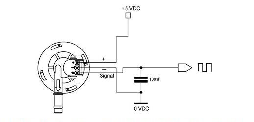
Everything is clear now! 5 Volts are perfect! I will not need any buffering to the PIC, maybe a pull-up resistor. But how does the water flow sensor works? I need to feed my curiosity. I was born with it. What is inside this sensor? A closer looks reveals that the top side can be rotated in respect to the bottom side, and it will open. And so i did... Inside, i found a sealing o-ring and the rotor. The rotor is a 6-fins plastic with 2 magnets attached to the shaft:
Judging by the size of the piece that the magnets are closer to, i suspect that there must be a Hall sensor hidden inside. So, as the rotor rotates, the magnets actuates the Hall sensor. The sensor will provide the pulses as shown in the connection diagram. Taking some results I know how it connects, i know how it works, now i need to see some results. I made a simple construction. A funnel is connected to a tube. the tube leads to an empty bottle. I cut the tube and i put between the flow sensor. i connected the power supply to my PSU, and the output to the oscilloscope. I start puring water into the funnel. Here are the results:
Ok, pulses... But how many pulses? The final thing that i need to find out is the pulse rate. How many pulses per 1ml? This is the question. So, i connected the sensor to the hose water supply. The water will fill a measuring container. The sensor pulses are driven to a pulse counter circuit. I will turn on the water and i will write down the pulse count for 100,200,300,400 and 500ml. Finally, i will count the time that it takes to fill 500ml, to calculate the water flow (lt/min). The pulse counter is a very old circuit. I made it when i was first learning CMOS chips and digital design. This is my very first digital circuit that i made when i was young. It counts pulses from a 555 timer, or from an external source (sleeted by the switch). When it reaches 999 counts, it arms a relay. the relay was supposed to detonate a bomb...
And here are the results of this experiment. I took 6 sets of measurements. In each, i measured the pulses for 100,200,300,400,500ml, and the duration in seconds: 
The first line indicates the time in seconds to fill the 500ml, and the calculated liters per minute from this measurement (Flow (lpm)). Then, there is a matrix with the following columns: The PPMl is the most important for me. This will show how many pulses i get per ml for a specific flow rate. For 0.7 to 1.3 liters per minute, the results are very encouraging. I can roughly come to the conclusion that this sensor sends about 1.8 pulses per ml. When i use it, i will use a flow control valve to have fixed flow rate (around 1 lt/min). Comments
|
|
 Contact Contact
 Forum
Projects
Experiments
Circuits
Theory
BLOG
PIC Tutorials
Time for Science Forum
Projects
Experiments
Circuits
Theory
BLOG
PIC Tutorials
Time for Science
 RSS RSS
Site design: Giorgos Lazaridis © Copyright 2008 Please read the Terms of services and the Privacy policy |


 Reddit this

