It is not really necessary to use a micro controller or a special IC to control a stepper motor. So, here i present a very simple and basic full-step stepper controller for a unipolar motor. If you do not know how stepper motors work and how they are made, what is unipolar and bipolar, or what is full-step, half-step and micro stepping, i strongly suggest that you read first the theory page "How stepper motors work and how they are made" that i wrote a few months ago.
The circuit
Here is the schematic circuit for the controller:
As you see, i only use the 4017 CMOS chip. This is a decade counter/divider. The input pulses comes from your pulse generator. Each pulse, will increase one count to the 4017. This will happen 4 times, for counts 0 to 3. When in count 4, the chip will self reset (from the wire Q4 to reset) and will start over again. The first 4 outputs (Q0 to Q3) are driving the 4 mosfets. Power the CMOS with 5 volts otherwise the mosfets will not work! This is very important. You can use whatever voltage for the motor, but for the chip you must use 5 volts! Not more. If you badly want to use more, then you need resistors for driving the mosfets!
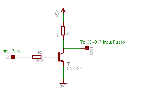
Notice that i have no interface for the input pulses. I suppose that the pulsing circuit that you will use, will have the same supply and output power as the 4017. If not, then i suggest you use the following circuit to drive the pulses to the 4017:
This will work for low and medium voltages. If your pulses are more than 12 volts amplitude, you may consider increasing R2. As for the mosfets, these are my favorites-yet a little bit expensive. They have some remarkable DC characteristics. Can handle up to 100 Volts, with the incredible 0.055 Ohms RDS(on)! The voltage drop due to the mosfet is ridiculously low. 22 amperes can go through continuously, while up to 88 amperes pulsed can be controlled! I like it.
How to connect the stepper motor
My stepper is unipolar with 5 wires - this means it has one common
From each mosfet, there is a pin output, a total of 4 outputs comes from the circuit. Also, notice on the right side the fifth pin. This is the power supply of the motor. This must have the positive supply, whatever it is. In my case, the motor has 12V coils and therefore my supply is 12 volts. This may change according to the motor power supply.
The first 4 pins, must be connected to the 4 coil outputs of the motor. You need to pay attention to the coil sequence. If the sequence is incorrect, then the motor will not rotate correct. It may go clockwise and counterclockwise with no certain order. In any case, the pulses from the above circuit are delivered in the following order: 1 - 2 - 3 - 4. It's up to you to find the correct coils of your stepper.
The fifth pin goes to the common of the coils. As i said at the beginning of this article, the stepper must be unipolar. This means that there is one (if your stepper has 5 wires like mine) or two common wires (if your stepper has 6 wires). If your motor has 5 wires, then the common wire goes to the 5th connector. If your stepper has six wires, then both common wires goes to the 5th connector!
There is also one case that your stepper has 8 wires. Most probably, you have an 8-lead stepper. This type can be connected both as unipolar and bipolar. Read this page to see how to connect the wires.
I wanted to know if this circuit can be connected on a CNC controller for inserting automatic disconnection of a PP or spindle motor with 2 phases . In practice, the signal is provided by the CNC controller ( dedicated port ) will speed up input basic data from the software ? Thanks so much.
Hi there, do you happen to have the price range for those mosfets, since my pulses are more than 12 volts amplitude and I need to increase R2.
<a href="http://blog.poscope.com/stepper-motor-driver/"></a>
@Agis This is a simple and classic schematic. If you cant read this schematic then you need to learn how to read schematics instead. It cant be any simpler.
At 2 January 2014, 11:14:51 user Agis wrote: [reply @ Agis]
Hi
I am interesting about this circuit but i have problem to understand the schematic (as novice)....It would be convinient to you to send me a 'classic' schematic of this circuit?
Very nice design!A smart engineer always keeps it simple for less inventive people. Is it possible to use the cd4017 i.c. for a cnc application as well? Is there a way to reverse direction? I'd like to cnc my dremel tool using something similar to your circuit.
@anhdbk Motor common goes to positive. Drain of 4 mosfets goes to the 4 wires of the stepper. Source of mosfets to ground. Drive the gate of the mosfets with a small 100 ohm resistor.
hey guy. i'm preparing for my final project.i use PIC 18f4550 to control stepmotor. my signal output from PIC very good. however, when i connect with motor to cotrol, motor does not operated. i think power supply for motor not enough.i want to ask you,i use irf540 to provide power for motor 12V-DC.how do i have to work?
At 6 March 2013, 18:29:08 user Nana wrote: [reply @ Nana]
What is the step angle of this stepper motor.I have the same one but it isn't mentioned on it. and when I looked on the internet NBN... I fount documentations but in chineese so I coudn't get the informations that I want.Thnx
I wanted to ask some advice regarding my cnc, I would like to know if "Simple Unipolar Stepper Motor Controller Full Step" in practice acts as a stepper motor driver 24 A. But I do not understand where can I pick up signals: dir (direction, step and enable (usually no one ever uses it.) Should I connect a L298 or another IC. Basically I need to automate fourth rotary axis, then the management is performed by "Colibri CNC" of Twintec (Italy).
@John Iacovides Do you mean the dot on the CMOS? This indicates where pin 1 is. I am not sure about a dot on mosfet. Is this a colored dot?
- Yes, always we provide DC power to CMOS ICs
@Giorgos Lazaridis
I am a little confuse and I would like your help. What the dot in the mosfet indicates?(In my mosfet the dot is on the 1st pin and not in the middle).
IRF540N IOR mosfet.
Pin1->Gate (I did to this pin output from CD4017)
Pin2->Drain (To this one,I put the resistor)
Pin3->Source (And this one directly to negative, despite the fact that is source)
And second do we have to power pin 8 Vss with negative power and pin 16 Vdd with possitive one?
I cannot see clearly the wireing on the breadboard, can i have images from all sides?
At 21 August 2011, 23:07:48 user Mike wrote: [reply @ Mike]
i have used CD4017BE and had hard time in the beginning to make it work but i found out that i need to connect PIN # 8 to the ground and PIN # 16 to 5 VDC.
After that it works good.
thank you the author for sharing his knowledge with us
hi again sir. I tried putting resistor (470 ohms) as what you've said and finally my cmos ic did not get hot anymore. My another problem was when I try to connect the motor,it didn't work, and as some electronics book that I have read,mosfet are very delicate to static charges,please help what should be done to prevent these damages because these stuffs are quite expensive to buy. Also can I replace these with medium power transistors such as the TIP31 / TIP 41? Please advise again. Thank you very much.
hi again sir.I had this problem regarding the driver. I used already the 4017 cmos ic and found out that its getting hot while i connected it with the mosfets ( I did not connected yet the stepper motor ). I used two kinds namely IRF740 and IRFZ44. Does these mosfets match with the 4017 ic? I also followed the schematic diagram provided in your webpage. Thanks again...
fernando, regarding the 1.3V, i strongly suggest you use STK chip (http://pcbheaven.com/circuitpages/Full_Half_Stepper_Motor_with_STK672). But for the 12V, i suppose that the only limitation is the current. The IRF540 are very tough guys. Most probably this will work. Share with us your results if you test it
your experiment looks more simplier, anyways I'm working on a semiconductor company and I had lots of stepper motors that are quite bigger and heavier. Does the circuit can run these motors? They are 5.1V
while the other one is 12.2V, and the worse is that I had this 1.3V stepper motor..Please advise..
Thanx for the info before, I'll check the following link :D
Uniquely your project is so simple frend :P . do your steppers that you use are for a high rpm or not? how about my mine? here I guide you to my stepper 12V, it say step per revolution is 48 and step angle 7,5. hearing that, does my stepper construct for high rpm or not? hoiya, in a fact I'm using BD139 to drive it And my PIC program drive it for double phase.
hi gumilard. this is a normal reaction of the motor. the maximum speed is mostly determined by the mechanical characteristics of the motor. if you are using a simple full or half stepper motor controller, then this will be the maximum speed. you may want to test a micro stepping that will definitely increase a bit more the speed, but do not expect an awesome increase. check these links:
- http://pcbheaven.com/circuitpages/Microstepping_Driver_with_the_Sanyo_STK672_080
- http://pcbheaven.com/blogpages/Product_Review_Linistepper
hi frend, I gotta a hard case at least for me. Mmm I want to increase an unipolar stepper motor (55M048D2U) 12 volt. when I try to increase pulse, The motor looks jammed. what should I do? oh yea, I\'m using PIC microcontrol to generate the pulse. Do that circuit can use for my stepper to? would you like to help me for all following circuit of my project?
At 27 August 2010, 2:53:44 user Ed K. wrote: [reply @ Ed K.]
I ordered a 4017 chip and used IRF630's mosfets. This was my first attempt at operating stepper motor. I used a 555 timer to generate the pulses. Trial and error with the motor phases connections finally got my stepper turning in one direction only. I used a small 7.5 degree, 5 volt motor. Great circuit for learning about stepper motor operation.

 Home
Home
 Projects
 Experiments
 Circuits
 Theory
 BLOG
BLOG
 PIC Tutorials
 Time for Science


 Contact
 Forum
Forum
 RSS
RSS


 Reddit this

