This is the basic idea of the PWM fan control circuit
The following project is a PWM fan control, especially designed to be used for PC modding. It is very easy to be built and it can efficiently control all DC fans to rpm as low as 450 rpm (the lowest limit has to do with the fan type and manufacturer). It uses ONLY one 555 timer and a few other components, and it can be powered also directly from the PC power supply, from the 12 Volts line. (see the molex pinouts and get power from your PC)
Advantages over other controllers
The complete circuit is composed by a 555 and 9 more cheap and easy to find components, and can be composed in minimal PCBs or prototype boards.
PWMs will generate a distinctive kick noise
Well, actually it does not send directly PWM pulses to the fan, although that was the original idea. When you PWM a fan directly, it causes some acoustic noises. This has to do with the torque kick. The PWM will send interrupted pulses to the fan. Each time a pulse hits, it will 'kick' the fan to revolve. This kick will cause a 'tick', and all ticks together will cause the distinctive sound when the fan directly connected to a PWM generator.
I tried several ways to eliminate this noise. The most effective one was to increase the PWM frequency. Higher frequencies generates higher frequency noises. Above acoustic spectrum (20KHz) no noise could be heard at all!. Yet, as you will find out later on this article, i was not pleased with this solution. I wanted to have also rpm feedback from the 3rd cable (tach) of the fan. Here is another High frequency PWM fan DC motor controller.
Lower frequencies on the other hand, could reduce this noise enough, but not eliminate it. I found a 2.4Hz to be low enough not to be so noisy, and high enough to control the fan efficiently.
No more kicking noise!
But still that was not a solution. It was rather a pit stop, because it was getting late and i had to go to sleep. The next day i came up with another solution. I would turn the PWM control circuit into a switching mode power supply! By controlling the voltage across the fan, someone can control the rpm. Using a PWM voltage regulator i could accurately and efficiently control the speed of the fan. The results where astonishing! The fan generated enough torque to revolve in really low rpm, so low that i do not intend to use. I could stall it by hand and the fan was capable to start again revolving in low rpm. And what about the 'kicking noise'? No more kicking noise!!! Absolutely not. Nothing. Quite like the breathe of a baby. And at lower speeds, as low as 600-700rpm... almost soundless.
The circuit in operation
Watch the following video to see this circuit how smooth and accurate can control the fans even in low rpms.
Back to the Tech-labs
The circuit
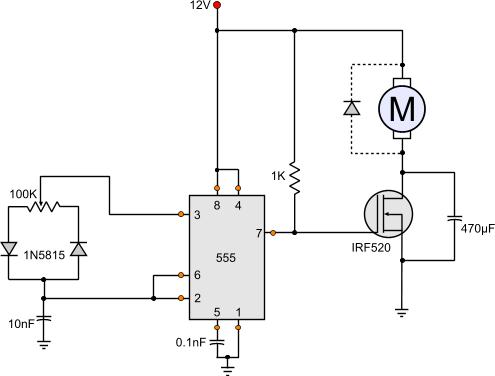
The circuit is based on the theory of the 555 connected as astable multivibrator, with a slight change. The capacitor will be charged and discharged from different ways each time. Through the left diode shall be charged, and through the right diode shall be discharged. Therefore, the charge and discharge times will be different while the frequency of oscillation shall be every time the same. The frequency will be calculated from the total potentiometer value (from side to side), but the duty cycle will be according to the position of the middle potentiometer pick-up.
The 555 will create a series of PWM pulses and will be driven directly to the gate of the MOSFET. The MOSFET is chosen to be big enough to carry enough loads, up to 9.2 amperes. You can choose a MOSFET according to your needs.
The MOSFET will generate enough power so that the motor will start revolving. The capacitor across the MOSFET is the solution to the'kicking sound'. The MOSFET will send to the motor pulses according to the pulses generated from the 555. If you remove the capacitor, you will definitely hear this annoying sound. The capacitor will smooth the voltage across the motor and therefore the power driven to it will be smooth, avoiding the torque kicks.
You can find more information about switching power supplies in this page
There is more! Speed control and rpm feedback from 3-wired fans!!!
The basic idea of this circuit was to have a 3-wire fan controlled with PWM and simultaneously have rpm feedback. There are of course 4-wire fans exactly for this application, but i already half have a dozen of 3-wire 120mm silent cooler master fans.
The problem is that when you send PWM to control a 3-wire fan, from the third wire you will no more get rpm feedback, but the PWM pulses itself. And this is because a pure PWM will completely cut-off the power once in each pulse. If you want to know exactly the reason for this, then go to the article "How PC Fans Work"
One idea was to use PWM to control it for a long time and then for a few time send constant current, as long as needed for a full pulse. At this time feedback could be taken. yet, this would require a microcontroller. This method is called "Pulse Stretching", and i have make a circuit to demonstrate this method. Go to the page "PWM 3-Wires Fan Controller with RPM feedback (Pulse Stretching Method)"
With this circuit, there is always a constant voltage across the fan and therefore feedback from the third wire can be taken at any time. But for simplicity, the feedback will be discussed in another circuit.
Watch the following video that demonstrates this circuit in operation, and the feedback pulses are shown in the screen of the oscilloscope.
@Nicos power is current multiplied by voltage
P = V x I
In theory, you have 3 x 162 amps allowed to flow that is 486 amps. At full current with 24V the output is 11664 watts, or 11,6 KWatts. But each mosfet has a max power dissipation capacity. This is calculated but the formula
P = I^2 x R (derived from the same P=VxI combined with ohms law R=V/I).
This is only theoretical and is drastically decreased dues to low turn-on and turn-off times. The mosfet gate has a parasitic capacitance combined with the pull up resistor it makes a nice delay circuit which eventually heats up the fet. To solve this you need to drive the gate with a fast mosfet gate driver
At 19 August 2015, 9:34:11 user Nicos wrote: [reply @ Nicos]
I built a PWM motor controller at 24V and I parallel three mosfet IRF1404, each 162A current 4m%u03A9 RDs ON resistance, 200W. How can I calculate the max current or power in Watts of the system output?
Should I suppose that Imax= 3 x 162A or Pmax= 3 x 200W or nothing of that?
Please help
I have tried with 470 micro farady capacitor across the mosfet. The mosfet heated up too much and affected the operation. I used IRFP150 mosfet. On removing the capacitor the mosfet was very cool but sound probelm. I used 24 Watt fan. Can you give the solution for it.
@Mike It would work but do not add the capacitor across the mosfet
At 9 February 2015, 21:13:18 user Mike wrote: [reply @ Mike]
I've got a question. Can I put there two light bulbs 12V/60W instead of the motor and change the MOSFET to dim the light? Would it be efficient or need any improvements if I do that?
Is there a simple solution possible to express the time or angle between a zero crossing point and the firing angle point of a by triac controlled 110/230VAC main-line to led-bulbs.
That I can have a trigger signal to a PWM controller in a dimmer circuit of each led-bulb.
Hi, Im using this circuit for a 12v 1.3A Cooling fan. The speed control is good but I have the "kikcing" noise when I set low speeds. When I was testing with smaler motors (.15A to .4A) there was no kicking sound. My question is: Should I replace the 470 micro farad capacitor for a bigger one (640 or 1000 micro farads)?
Hello, I've try this and works, only cap's are different but nothing bad, one thing, for the rpm feedback I didn´t use the pic, instead i use a low pass filter on the feedback to filter the pwm and only see the rpm feedback, i works!, justcalculate an RC Low pass for 100-200 HZ (try ti find your good point) and that´s it, problem solved
@Giorgos Lazaridis thnx i will surely make the changes but when i remove the cap the fan starts to stutter :( and doesn't rotate normally but starts kicking and it sounds unpleasant :(
I connected the circuit as given and i used an adapter of 12v and 1.25A.the circuit worked perfectly and the only change i did was using diode 5818 instead of 5815,the circuit worked perfectly then after a few days the fan started running at max speed even after changing the pot's resistance.so i changed the pot and the ic 555 but still the fan runs at max speed :( plz help
I wonder, would this (or any of the other 555/PWM projects of yours) suit the following:
Controlling the speed of a simple 5V DC motor (one that you would find in DVD/CD drives to eject/pull back the tray), that I have been successfully running on a 9V DC Power Supply?
To put it into perspective: I am using this old DVD Drive to act as a Projector Dowser, but would like to control the voltage/speed of this motor, so that I can "sneakily" black out the projector.
But wait, there is more :). I am currently using these two momentary toggle switches (one green - "open", i.e. Projector Beam visible, and one red "close" i.e. move the tray in the way of the Projector Beam, BOTH rated for 12V). These are basically connecting the motor to the Power Supply (as Momentary / ON switches), are wired parallel, and in their OFF state provide power to the LEDs in the switches themselves... i.e. nothing is pressed = both LEDs are lit up, once either is pressed, the button in question goes dark (while this seems to be counter intuitive, it is a way to FIND the switches in dark theatres ;)....
so far, I tried your LED circuit (but admittedly without resistors in line with the LEDs): http://www.pcbheaven.com/circuitpages/LED_PWM_Dimmer/
The result was that it lit up, but as soon as I turned the potentiometer, everything went off... So I assumed the transistor to be dead and got a new, bigger one (Darlington TIP122G)... this one did see the circuit working, but not dimming at all.
Anyway, I stop the rant right here... I clearly do not know enough about what is likely to stop this circuit from working, or how to test what works or what doesn't... but I am eager to learn ;P!
Please let me know if any of this sparks an idea or two...
Im thinking of using this for a small gokart that has a fried pwm....
it has two motors at 24 v and they can draw up to 19A each.
Any suggestions for mosfets that could handle this kinda current at 25V with minimal cooling?
Old pwm had two mosfets and a gigantic shottky diode...... im guessing two channels but the board was sealed in some sort of plastic and its impossible to even work on.
@PETE 555 can operate safely at 15V. But 10 amperes for such a simple circuit is too much. For high amperes you must remove the 470 capacitor!
At 14 April 2013, 8:22:29 user PETE wrote: [reply @ PETE]
PWM:
1.)What input power supply voltage(V)RANGE can I use it with ? (0-12V maybe ?)
2.)What is the maxium amperes of the motor IRF520 is it datasheet max:9.2A DC-motor ? (Broken PCB if I use 10A motor ?)
I have made various tests and as already thought these two fast diodes considerably slow down the speed of rotation. Without diodes excellent results.
I replaced the 1K resistor with a 5-ohm, then at the end I 've eliminated completely, so as to absorb the amperage required by the engine without any restriction.
I finally figured the electrolytic capacitor:
20000 / (12VDC / 4A) = 6666 micro farad (this value is not standard and I will use 'one from 6800 microF).
@Giorgos Lazaridis I assembled the scheme but the engine does not have speed variations, there is only a slight variation insignificant. I was thinking of replacing the potentiometer with a 10,000 ohm, because it seems strange that there is no change in velocity. In the test I used a 220K 's only one available. Can I use a trimmer with values %u200B%u200Blike 47K or less?
The mosfet I used a IRF640 (200V 18A), so I think that the cause is just a potentiometer.
Interesting this circuit "Linear DC motor speed controller using a simple PWM switching power supply mode", ideal for the welding machine so as to deliver the wire to be welded. I just wanted to ask a very simple question: out of the rectifier bridge (where the scheme will be applied) I get 14 Vdc and I was wondering how can I do to lower the correct voltage.
14-12 (High voltage PWM) = 2 V difference.
I 18 A max.
R = V / I = 2/18 = 0.11 ohm
W = V * I = 36 W
Obviously fetch ("three-speed notches) 's essential that I need and then I think I'm about 5 6 A, maybe less.
@uros if you remove the fet the 555 keeps frying? If yes, then the problem is the mosfet itself, the gate is shorted
At 17 January 2013, 2:20:28 user uros wrote: [reply @ uros]
Hi i am having a few problems with this circuit.....the 555 keeps frying, sometimes even without the load......i am using the irf530 to control a 12v 1A motor(small drill)...would a resistor between the gate and cmos help? any suggestions? also does anyone have a pcb drawing for this?
thank you
At 4 November 2012, 14:29:12 user cagri wrote: [reply @ cagri]
Hi,nice solution but I note the comments about non-linerarity.
There are many differing 555 specs. and whilst the CMOS version might not mind the 100Kohm VR it is likely to be too large compared to the switching diode charateristics for 'linear' operation. Get the current into the mA region to improve the timing characteristics.
Instead of a mosfet, i used a bjt and instead of getting output from 7, i get it from 3. Also instead of a 12V power supply i am using (for now) a 9V battery. I use a bd237 Vcc->[collector] [emitter]->GND and [3]->56%u03A9->[base]... it works but it makes noise. Adding a 470%u03BCF across the bjt stops the noise, but now the fan goes full speed :(
Hey dude thanks a lot I made an adjustment to the diagram an instead of using an irf I used an tip102 bjt darlington aray, it´s for me easier to use be cause of the control I made whit youre help it is going to be used by childrens, thak you for the useful information and congratulations for youre work.
@Vytenis it is normal that the frequency is changed, the 555 is not the best solution, it is just a very simple solution for this. If you find some way for the linear problem, please post us the results.
I did some monitoring on the circuit and found some interesting things. Firstly, the output from 555 seems to be not very stable - the waveform changes a lot (http://www.filefactory.com/file/oacr1qwe95b/n/20120427012_jpg), although i did put the 0,1nF capacitor on pin5.
Also, it seems that the frequency of the PWM increases when i slide the potentiometer to one side (max or min) - which is a bit strange, since the total resistance stays the same :/
And yes, now that [vrga] mentioned it, logarithmic pot may not be the answer. I will try to fiddle a bit with the circuit if I can get some decent waveforms on the oscilloscope.
At 26 April 2012, 18:53:27 user vrga wrote: [reply @ vrga]
@Vytenis things is, using a logarithmic pot would just make the timer part control logarithmic. after a lot of fiddling, i realised that the timer itself is fine, adding that capacitor does not affect that particular circuit. what it does affect however is the capacitance between the gate and source/drain of the FET. which results in longer turn-off times for the FET.
one solution i did find was to increase the load or reduce the cap. you'll have to fiddle to get the proper values for the cap. If you plan to use this to control multiple motors/fans, this might be a self-solving problem.
another solution *might* be to use an ordinary BJT transistor instead of the FET, but i have no clue as to the details of placing it instead of the FET.
Hi,
thanks for the great info - this circuit seems to work fine, but like [vrga] said it looks like the control is logarithmic. Maybe I could use logarithmic (instead of linear) potentiometer to correct for this effect?
I resolved the fan RPM issue by using PNP instead of NPN. When a PNP is used, the fan black lead is connected directly to ground. The fan red lead goes through the transistor to V . When the black lead is connected directly to ground, the RPM (yellow) circuit works correctly.
@vrga then you will need a linear supply, so you need the capacitor. but this means that as the voltage drops, the torque drops as well, and so there is actually no solution to this problem. during my tests, i had a 1800rpm fan which i could run down to 200rpm with pwm, but only 800-900 rpm with voltage control.
At 20 March 2012, 12:14:48 user vrga wrote: [reply @ vrga]
@Giorgos Lazaridis thats the thing :D i want the RPM feedback, as i dont trust my own skills when assembling the pcb, nor my soldering skills all that much.
@vrga if you do not want to get feedback rpm from the fan, then you can safely remove the large cap from the mosfet. it is there only for 3-wire PC fans which provide feedback wire (the yellow one)
At 19 March 2012, 10:13:09 user vrga wrote: [reply @ vrga]
'lo, i've been trying to get this circuit to work properly for my use recently, as i plan to run 3 fans off of it at once. the basic issue is that without the 470uF cap, i have the full range of the pot at my disposal. But, if i add the cap (slightly bigger on my end, 680uF), the pot basically turns logarithmic. i have a very small wiggle room at one end of it which goes from 1% to 90% within basically a 1-2 degree turn, if that. If you have any reccomendations on how to fix that in some way, i'd appreciate it :)
Also, i'd reccomend that the 10k resistor is always added between the discharge pin and the mosfet's gate, since if it isnt there, and you add a capacitor parallel to the load, not the mosfet, well, two 555's were fried in identifying that "issue" :p
@gusthi manual hmmm it does make sense, but i wonder, doen't the mosfet get hot? have you tried the series inductor? i'm preparing a switching circuit for a 20A motor (the starter for a bike) so i might face the same problems... I won't try this without the coil though.
after 6 deep fried 555 salad, i found the a working recipe which can handle the high torque windshield motor.even after adding rc snubber (.2 %u03BCF 50 Ohms resistor) didn't changed the fate of the 555. adding a 10k resister in between the gate and the 555, it works without any issues. i am not sure the 10k resistor is giving the full performance of the MOSFET. still i am very happy after few days effort to get the motor working. let me know if this makes any sense.
@gusthi manual then you need a snubber. You can get a quick idea from wiki (although i do not encourage people reading through this site).
http://en.wikipedia.org/wiki/Snubber
An RC snubber might work for you. Try an RC snubber across the fet first.
As for the coil, i'm really not good at this. Nevertheless i know that an inductor can add a delay in the current increment and therefore it can cut the spikes. Use a thick coil wire, thick enough to stand the motor current (you need therefore to know the motor current). Then, make a coil on an iron rod some 50 turns (might work with less as well). Connect this coil in series with the motor.
@gusthi manual this motor will draw some 2-3 amperes, and will cause a very large spark every time the mosfet is off. This will ground through the 555. First of all, do not use the 470uF capacitor. Also, use a shottky 1A (or more) diode across the motor reverse-biased. If the problem remains, you will need to add a filtering coil in series with the motor to decouple the supply.
@Matej no this won't work like this. you need to make something like a dc controlled pwm with a microcontroller. Or try this:
http://www.pcbheaven.com/circuitpages/Voltage_Controlled_PWM_Generator
i tried to use this circuit to control a windshield motor and without any luck.
i am using the IRF 540 get more amperage for the motor, but every time i try to connect to the circuit,it works for couple of minutes and then 555 gets fried.
anyone can help me in this matter? i already fried few 555's :(
MOSFET still good. isn't the IRF 540 supposed to take more than 10 amps?
Very nice work! Could this circuit be modified to do the following:
INPUT: humidity sensor(V=5V/DC)-linear response(2 - 3,5V at 50 - 90% rel. hum.)
CONTROLLED OUTPUT: 3×12V DC fan (300mA, 7V starting voltage)
...and the following is: turn on the fans at set value (50, 60, 70, 75 and 80% rel.hum.) and gradually slowing the speed down until rel. hum. falls for 5% and than off (bellow 7V, lets say 5V).
Thanks.
At 9 February 2012, 11:26:48 user Grant wrote: [reply @ Grant]
@Giorgos Lazaridis Thanks. I actually just found a 10.8 v dremel 8000 that is suppose to do what I am looking for, but I have read some bad reviews on the speed controller not working consistently. I am going to look at it. I will let you know if I build the circuit.
@Grant first, i would stick to IRF540, you get 22amps for little amount of money more. I usually use the 540 for my projects. As for motors, i have never searched for one with these specifications. The capacitors must be like 470 or 1000uF, higher voltage than normal (higher than 50volts).
Unfortunately i am not very good with motor control, but i do know that you may (probably) need a coil in series with the motor. Do you have access to an oscilloscope? I'm interested to see the results from the circuit. Test it with the capacitor parallel to the motor (remember to remove the 470 cap from the schematic!!!) and the diode (like 1N4007) reverse-biased again parallel to the motor. If something blows such as the mosfet or the cap, you may need a filter (coil) in series. Please tell me the results.
At 6 February 2012, 14:15:08 user Grant wrote: [reply @ Grant]
@Giorgos Lazaridis Thanks for the response. I really appreciate it, as I am a completely inept at calculating the proper values for the components. I think the motor is one of my big problems. Do you know of a good high torque low rpm motor that I should use. If I stick with this motor would an IRF530 FET work, given the amps. Also, what capacitor would you recommend trying across the motor. I also saw this pwm controller based upon variable voltage supply and pwm. http://www.brighthub.com/engineering/electrical/articles/86517.aspx Do you think this will work better? the only problem is that its components and duel power supply requirements will not be compact. Thanks again.
@Grant i am not quite sure if this a proper circuit for your application. first of all, you need to remove the 470 cap since you do not need feedback. You cannot get low speeds with the cap. Also, a motor is an inductive load which it will generate spikes. You need to add a diode reverse-biased across the motor (as shown in the schematic). Also, a large capacitor across the motor will also help a lot. A voltage suppressor is a component which will clear the spikes, you may not need one though.
Also, consider using a larger fet because you will need 13 amperes for this motor.
At 5 February 2012, 20:35:48 user Grant wrote: [reply @ Grant]
I have a similar issue as the post by Nick on 6 August 2011. I am trying to make a grinder (like a dremel) with full speed control 100 to 5,000 rpms. It has to be compact and cordless. I was using this motor http://www.mabuchi-motor.co.jp/cgi-bin/catalog/e_catalog.cgi?CAT_ID=rs_540sh and this pwm controller http://www.theledlight.com/pdf/zane/Four-Wire-DC-Motor-Speed-Controls.pdf But I cannot get consistent low speeds. I would like to use your circuit. Would you mind providing any suggestions on the motor and details regarding how to add a "Voltage Suppressor and some Capacitors if the current and the inductance of the motor generate high spikes." Any help is greatly appreciated.
At 23 January 2012, 23:08:07 user Pete wrote: [reply @ Pete]
@Bill Gaytes
Good point! Would it help to have the capacitor in parallel with the motor (rather than the fet)?
WTF? This circuit is horribly wrong! What is that 470uF cap doing there? You realize that during every cycle, the cap gets shorted by the FET and sends up DOZENS of amps through it? Your version only didn't go up in smoke because the FET is robust enough to take the punishment. But the cap will eventually die.
The standard 555 PWM circuit is ok and works well, but that cap is just stupid. You clearly don't understand basic circuit theory.
@minhbh first of all, you need to use a bugger capacitor for such a motor. Maybe something like 2200uF. I used the 470uf for a motor that draws 350-400mA.
To set minimum voltage level, you need to make the potentiometer asymmetrical. This is how you do it; You simply add a resistor between one diode and the potentiometer. First, replace the pot with a 50K, and then add a 22K resistor between one side and the diode. Look here:
http://pcbheaven.com/circuitpages/High_Frequency_PWM_Fan_Controller/
Go to the second schematic. There is an R4 diode between the left side and the diode. This is exactly what you have to do. Make tests to find the proper resistor value.
At 3 September 2011, 8:48:48 user minhbh wrote: [reply @ minhbh]
I made it, run very fine, so many thanks for the circuit
But I want to make circuit run from 7V to 12V, not 0-12V (my current circuit run from 1.2V - 11.9V), my motor run at 1.8A. How must I do? Thanks
@Nick i need to know the current and power of the motor to tell you. The IRF can handle up to 9A. The circuit can operate your drill (if the current of the motor is not that high enough). The low rpm has to do with your motor. You may need to add a Voltage Suppressor and some Capacitors if the current and the inductance of the motor generate high spikes.
At 7 August 2011, 2:03:31 user Nick wrote: [reply @ Nick]
Hi, I\'m new to electronics.
I\'m looking at building a PWM to control a 12V cordless drill motor and be able to get it to low RPMs, arround 4RPM. Would this be a good PWM to do this?
I have a fishing troaling motor. It operates from 12 to 24 VDC. I would like to control the speed of the motor. Can this PWM circuit work ?
If not what can be done to make it work ?
Thanks !
Dear Sir,
First off all thanks for posting this, second i was wondering if it is possible to connect ramp input instead of the potentiometer in the circuit so the motor accelerates autimatically?
if yes please Let me know ASAP and i'll be so thankful.
Kind Regards,
Sari T.
Hello, I wanna use this circuit for 5Vdc using a battery of 5000mah. Is the circuit is only made to operate at 12V or it could be lower like 5 V and also I would be using a 5Vdv fan. Suggest me...Thx
Kammenos, with this circuit (on my fans) there is a very small margin between nearly-silent and stalled. I'd be afraid that just a little dust, or maybe just the circuit parts getting hot and changing values, would stall the fans if I kept them set to a silent RPM.
Anyway, I've decided to just go ahead and see what happens if I PWM them, so I'm going to use your circuit here:
http://pcbheaven.com/circuitpages/High_Frequency_PWM_Fan_Controller/
(I'm using the second circuit on that page -- the one for 3-wire and 2-wire fans)
Hoosh777, this is not a problem, unfortunately, this is normal operation. This circuit sends not PWM pulses to the fan (as you have already notice). Instead, it uses PWM to change the voltage across the fan, which is a nice way (more efficient than others) to do it, but still carries the bad habits of voltage fan controllers. Fans have a lower voltage limit to which they operate. With pure PWM you can control your fans even lower, down to 300 rpm for example, but with this, you cannot go very low, always depending on the fan. The thing is, is there any particular reason why you want to go too slow? I have 4 120mm fans with PWM controllers in my PC, but i never run them lower than 1000rpm.
I built this using the IRF510 (that's all Radio $hack had). The one I got is made by International Rectifier: http://pdf1.alldatasheet.com/datasheet-pdf/view/68158/IRF/IRF510.html
The reason I wanted to avoid using straight PWM on my computer fans is because they are 2-wire fans, and I've read that using PWM on a fans' power line can damage the circuitry inside the fan (they're also ball-bearing and I heard it can cause pitting on the bearings).
So putting a cap across the MOSFET is a great idea.
The only problem is that as I'm turning down the pot, the fan slowly speeds-down, but at a certain point it just flat cuts off. If I disconnect the cap across the MOSFET I can go down much slower before the fan stops spinning.
Any ideas on how I can make it keep spinning at a slower speed?
It's a really awesome circuit, and I'm ready to order all the parts I need to build a 4-fan controller to mount in my computer -- if this problem can be solved.
I'm an electronics beginner.
Thanks a lot for all the work you put into presenting this to us.
At 28 January 2011, 22:06:13 user Rainer wrote: [reply @ Rainer]
Hi,
Thanks. Will do.
This are the fans I am going to use with 3 wires, becuase that is what I get here :-)
The difference is that, the one you are looking to changes the speed by altering the voltages. The new circuit that i suggest use pure high frequency PWM. Prefer it. It has better stability and of course is more efficient. And also wider operation range in speed adjustment. Your 2000 rpm fans may have problems running in low speeds. Prefer the high frequency PWM
At 28 January 2011, 21:18:32 user Rainer wrote: [reply @ Rainer]
Hi,
Thanks for the prompt reply.
Yes I meant normal 12V PC fans. The ones I have do 2000rpm and I want to be able to test different speeds through the radiator.
Question: ¿ Is the diode in parallel absolutely necessary and if yes which type ?
1N4148 will also do fine. With 9V, the circuit will work ok. The problem will be maybe with your fan. Usually, PC fans are rated 9V and they carry a brushless motor. If you find a 9v motor then it should work fine. Prefer a brushless motor, but a normal DC motor will also work.
At 1 November 2010, 17:11:23 user Omer wrote: [reply @ Omer]
Also, I can not seem to find 1N5815 diode anywhere online. Will a 1N4818 Diode work in place of 1N5815?
At 1 November 2010, 16:34:48 user Omer wrote: [reply @ Omer]
Hello. I really like this circuit. My question is that will this circuit work with a 9V battery instead of a 12V. What will be the specs of the motor that I can in this circuit if I go with 9V battery
Well Mario, if i get it right, you want the speed to change according to the temperature. This is not the proper circuit for this purpose. You should instead make this one which has a DC voltage input instead:
http://pcbheaven.com/circuitpages/Voltage_Controlled_PWM_Generator
I made this circuit to examine such a situation.
At 1 November 2010, 3:38:29 user Mario wrote: [reply @ Mario]
Could this circuit be modified to accept, instead of the potentiometer, a standard 10K thermistor? What components would need to be changed?
AtiFan, the switching power supply will deliver only the required power to the motor, while the linear controller will dissipate the rest of the power to the heatsink of the transistor. The efficiency of the linear controller is way lower than the efficiency of this circuit. Take a look at this article:
http://pcbheaven.com/blogpages/PC_Fan_Controlling_Methods/
what is the advantage of the pwm switching fancontroller (http://pcbheaven.com/circuitpages/PWM_Fan_controller_using_a_555/) instead of chaning the voltage in other ways like http://pcbheaven.com/circuitpages/Simple_Linear_Fan_Controller/
What do you mean ff? Flip flop?
The resistor at pin 7 is used as pull-up, because the internal discharge transistor (collector) of the 555 would be on air without it.
The cap at pin 5 is used for parasitics and can be totally omitted. Pin 1 must be connected to the ground either way.
The cap at pin 6 is the one that will determine the frequency of the oscillation.
I do not understand your last question about the 2 resistor... Please rephrase.
At 11 October 2010, 8:19:17 user jim wrote: [reply @ jim]
what is the functions of the ff.
resistor at pin n0.7?
capacitor at pin 5 and 1? and capacitor at 6 and 2?
in able to set the ic555 into a astable mode we have a 2resistor but why do you have to disregard the other resistor 2??
Yes it is possible. You will need something to regulate the input to 12 volts, like a zener for example. You need to have in mind though, that you will need more than 12 volts for a regulator to start regulating at 12 volts. An 7812 for example needs at least 14,6 volts. Depends on the input voltage (which i suppose it will not vary from 12 to 48).
At 30 September 2010, 7:44:06 user dean wrote: [reply @ dean]
Is there any way to make the input accept between 12-48v and output 12v 400ma? If so what would I need to change to make this ?
Hi neeraj,
there is no specific reason for using the pin 7. It was a test that i had made a long time ago. You can use another connection if you like, but this one works as well.
As for the switching off, pin 5 is not a good idea. Instead, i would use a transistor to control the power of the 555, exactly as i have done in this circuit:
http://pcbheaven.com/circuitpages/Two_Speed_Temperature_Fan_Controller/
T1 controls the power of the 555. As a matter of fact, you can use a part of this schematic (T1-555-D1-D2-R5-C1) and you will have your controllable PWM generator.
hi thank for the support for PWM circuit but i have a small question why you have used discharge pin in place of output pin for the PWM out is there any specific reason for this.
and if i want to switch off the pwm generation at a predefined time for this circuit can i do it by pulling down reset pin with a transistor or suggest me any good idea for this. thanks in advance.
Hello kerororo. 250mA is way bellow the mac current (this mosfet can carry up to 8A if i remember correct). so there is no problem about the current. The 555 works? Do you get pulses out of it? If you do, then most likely the mosfet is fried.
For the diode, you can use the classic 1N4004 or bigger.
the circuit worked perfectly for the first few tries but then on the 4th try, there was no more pulses(the fan runs at max). Did I fry my ICor is there some other problem? My fan takes up a lot of current.. 0.25A to be exact. Is this over the specs of this circuit?
Can a protection diode connected in parrallel to the fan solve the problem assuming that it is back current due to emf? What kind of diode and rating would i need?
Stian i have exactly what you need:
http://pcbheaven.com/circuitpages/Two_Speed_Temperature_Fan_Controller
Starts at a specific temperature at low speed (PWM controlled again) and runs at full speed at a higher temperature. I have it installed in my workbench PC cabinet.
What would I do if I wanted to use a temperature sensor?
I asume this circuit will speed up the motor if the resistance decreased.
I would need something that would start the motor at 60C and run it full speed at 80C.
Hello PDS,
I really like your question! Thanx!
Indeed, the pins 3 and 7 seems to be reversed. It was a test actually inspired from another circuit (that I do not really remember the page). I suggest you read the theory of operation of the 555 first (http://pcbheaven.com/wikipages/555_Theory/). In this page, you will see what is inside the 555. The pin 3 is driven from the Q of the FF through an amplifier, while the pin 7 is connected to the collector of a transistor that has the emitter grounded. In normal condition, this transistor would discharge the capacitor when -Q was HIGH. But in this circuit, this transistor will sink the gate of mosfet instead. I have answer half of your question. As for the pin 3, it will effectively discharge the capacitor when it is LOW. Moreover, if you notice, there is NO external power supply to charge the capacitor, as exists in a normal connection. That is because the same pin3 will charge the capacitor when it is high. Neat eh?
At 11 March 2010, 22:29:54 user PDS wrote: [reply @ PDS]
I'm a little confused. Sorry for the basic question, but I've built this circuit, and it works beautifully. I had to swap a 1uF cap instead of the 10nF as suggested for my particular fan, but I get a smooth speed variation between almost stalled and full speed. (Average voltage from 5V to 12V.)
However, when I compare this circuit to a standard Astable Multivibrator, pins 3 and 7 appear to be reversed (?). Typically, pin 3 is the output and pin 7 is the discharge. I understand the variable resistor and diode change, but how can this work with the output swapped with the discharge pin?
Sorry if this is a dumb question, but I'd like to understand *how* it works as well as using it myself. Great write-up BTW - even *I* could follow it.
Lanz:
The 470 capacitor needs to be placced across the mosfet. That is the right place. For better control, you can change the frequency by adding larger capacitor in place of the 10nF (eg 1 micro farad instead), or with larger potentiometer value (eg 500K). That shoud fit you just fine.
For LED dimmer, you only need to remove the 470uF capacitor completely and add the correct resistance according to your LED configuration you use. Check out the following pages for this:
http://pcbheaven.com/wikipages/LEDs/
http://pcbheaven.com/drcalculus/index.php?calc=leds
At 10 July 2009, 9:19:19 user lanz wrote: [reply @ lanz]
Finally it works for me.But still got some problems:
1)I test it without the 470μF Cap,there is kicking sound like what kamenos said but the difference in speed can seen very well with every turn of the VR.
2)I test it with the 470μF Cap placed parallel across the motor like the circuit b4 this and second time at the mosfet like the circuit above,the kicking sound is no more but the speed differ only slightly(not nice).
I like the 1st one but there is a kicking sound.How to solve this problem?
If want to use as a LED dimmer,where to modify?
At 10 July 2009, 9:18:25 user lanz wrote: [reply @ lanz]
Finally it works for me.But still got some problems:
1)I test it without the 470μF Cap,there is kicking sound like what kamenos said but the difference in speed can seen very well with every turn of the VR.
2)I test it with the 470μF Cap placed parallel across the motor like the circuit b4 this and second time at the mosfet like the circuit above,the kicking sound is no more but the speed differ only slightly(not nice).
I like the 1st one but there is a kicking sound.How to solve this problem?
At 10 July 2009, 5:30:38 user lanz wrote: [reply @ lanz]
Thats why maybe it doesnt work on my circuit.How to test the output on multitester,volt reading or current reading?
Oh, and as for the capacitor, it may be omitted if someone wants PWM for the motor. If the motor kicks (the distinctive kicking sound) then the large capacitor must be connected. It is across the mosfet now.
My apologies for the mistake. The circuit was copied in a hurry and was also the first one.
1 pF = 0.000001 uF;
1 uF = 0.000001 F;
C = 10 pF => 0.000000000010 F
R = 100 K => 100000 OHM
R x C = 0.000000000010 x 100000 = 0.000001
F = 1.44/(RxC) = 1.44/0.000001 = 1.440.000 Hz (1.44 MHz)
Check your math.
The minimum value of C to 555 works correctly is 1KpF (1000 pF) and the 470uF cap across the motor is not correct for a PWM circuit.
lanz:
1. The protection diode could be a general 1N4001 diode, but if you use the 470UF capacitor, you do not need it.
2. If you want to use a fuse protection, you should put it in series to the circuit. The circuit itself draws just a few mAmps, thus the fan will determine the fuse. You could as well calculate the fuse by the IRF520 capacity that is 9.2 amperes. In that case, you could use a fuse around 8 Amperes.
3. From pin 8 or 4 of the 555, a resistor of 330 Ohms will be connected and then the positive pin of the LED will follow. The negative pin of the LED will go to negative pole of the circuit.
4. I am sorry this cannot be done with straight-forward way. You could use a digital potentiometer circuit or IC, but that would be not a nice solution.
At 29 June 2009, 7:38:49 user lanz wrote: [reply @ lanz]
1)What is the protection diode's value that to be fixed parallel to the motor?eg.like 1N5815 for the left diode.
2)If i want to fix protection fuse,the maximum capacity of the fuse must be how many ampere?How to check it using multitmeter?
3)I want to add a LED as an indicator showing the circuit is working and the fuse is not blown.How to modify the circuit above?
4)Can the potentiometer replaced with any pushbutton switch?
Example-Two pushbutton switch is used to control the volume of a sound.
One to increase and one to decrease the volume.
Can this system applied in this circuit?
If can,how is the circuit will be?
Yes indeed, different fans or loads will require different PWM frequency. If the load draws too much current, it could be that the frequency should be increased (decrease the cap value) and vice versa.
At 11 June 2009, 21:37:45 user Tiki wrote: [reply @ Tiki]
Nice and is working, but with my Glacialtech fans i needed to replace the 10pF with a 47pF to get a large and smooth area of control.
Yes no problem!
The circuit will draw as much current as it needs. If there is no short-circuit, all will work just fine. You could for security reasons add a quick acting fuse in series to the power supply if you may.
At 11 June 2009, 4:50:25 user Lanz wrote: [reply @ Lanz]
Can i use this circuit to control my car\'s fan speed.Can it support high current from the car battery?
Hi XTAL.
The purpose of this project was (and is) the PWM signal generation. That's why the capacitor (470uF) is added at last. This project can be used in general for example dimming LEDs. Also, this project is a small research for the next circuit that i will demonstrate (hopefully this weekend). My PC box has 4x120 fans and 2 computers inside, as well as some peripherials like a router, switch, electronic staff....
Now that the fan\'s tach signal can be used by the motherboard, how about using the motherboard\'s fan control output to control the 555 circuit? There would still be a need to adjust the min speed for each fan to create a broader speed range than would be possible using the motherboard\'s fan speed output alone.

 Home
Home
 Projects
 Experiments
 Circuits
 Theory
 BLOG
BLOG
 PIC Tutorials
 Time for Science


 Contact
 Forum
Forum
 RSS
RSS


 Reddit this

