
|
 Home Home
 Projects Projects
 Experiments Experiments
 Circuits Circuits
 Theory Theory
 BLOG BLOG
 PIC Tutorials PIC Tutorials
 Time for Science Time for Science
|
| ||
|
21 March 2009 Author: Giorgos Lazaridis LEDsLED History During 1907, the British experimenter H. J. Round of Marconi Labs discovered the Electroluminescence phenomenon. It took no more than 13 years from that year when a Russian scientist named Oleg Vladimirovich Losev created the first LED. However, it took several decades fot the LED to find practical usage, as the alloys used emitted infrared light. In 1962 by Nick Holonyak Jr. while working at General Electric Company, discovered the first visible spectrum LED. Therefore is he called "the father of LEDs". LEDs were very expensive. The first that organized a mass production was the Monsanto Corporation in 1968. They were the first mass production red LEDs indicators! Hewlett Packard followed Monsanto Corporation and produced LEDs too, with alloys taken bought from Monsanto Corporation. How LED works Like a common diode, the LED (Light Emitting Diode) consists of a P-N contact. When a P-N junction is forward biased, current flows within it. This current flow will cause electrons and holes to move is a manner that an electron will move to fill a hole. When this happens, the electron will fall to a lower energy level and this will release an amount of energy in the form of photons. In a larger scale, those photons will produce light. A LED will emit a colored light not because of it's package color as many people used to believe, but because of the emitting wavelength. The wavelength that an LED will produce depends on the material used to form the p-n junction. The materials and the colors they produce are shown in the following table:
How to connect LEDs LEDs are diodes and to light an LED, it must be forward connected. This means that the anode of the LED must be connected to the positive pole of a battery, and the cathode must be connected to the negative pole.  This is how to determine the anode and the cathode lead of an LED Determining the anode and the cathode of a new LED is not very hard. The first way is from the length of it's leads. The anode lead is longer than the cathode lead of the led. Another way that is only possible if the LED package is round, is to find the sliced side of the LED. If you look it from the bottom side, you will notice that it is not completely round. There is one position where the circle is 'sliced' a little bit. The lead that is close to this slice is the cathode. Another possible way is to see inside the LED. If this is possible, the inside pins can be seen. The small one is the anode and the large one is the cathode. The leads could also be distinguished from its color (when available). The red is the anode and the black is the cathode. If the LED is used, then you should apply voltage to its leads to determine the anode and the cathode. The simplest way to light an LED, is to connect it through a resistor to a power supply as follows: 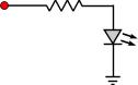
Extra care should be taken when connecting the LED. If it is connected with the cathode to the positive side of the power source, then it will not light and it will behave as an open circuit , as any normal diode would do. LED protective resistor calculation As you may notice above, the LED was not directly connected across the power source. Instead, a protective resistor reduces the current-flow in the circuit. This is because LEDs are very sensitive to overcurrent. 10% current above the nominal, will significantly decrease the lifetime of the device. Greater current will destroy the LED within seconds. In order to calculate the protective resistor, we need to know the specifications of the LED. The most common LEDs comes with a rating of 3.6Volts 30mA (for white LEDs) but this can significantly change for special LEDs like high brightness LEDs. In this case the ratings should be known from the supplier. For our convenience we will suppose that the LED operates at less than 3.6Volts and draws 30mA current. We suppose also that the power supply is 9volts. The resistor can be calculated using ohm's law as follows:
In our example: R = (9 - 3.6)/0.03 => R = 180 Ohms. The value 0.03 that we used for current is the 30mA converted into Amperes (10-3). You may find a unit converter here. LED protective resistor calculation for more LEDs But what if we have more LEDs connected? First of all we have to distinguish two types of LED connection. The first LED connection type is the series connection and the second is the parallel connection. There is also a hybrid of those two types called mixed connection. One by one, those types are explained below. LEDs connected in series When the anode of one LED is connected to the cathode of another LED and so on, this is called a connection in series. Three LEDs connected in series are shown in the following schematic: 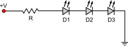
The following rules applies to this connection type: Suppose that we want to light the three LEDs above and the voltage is 24V. Each LED requires 3.6V @ 30mA power to operate. First we calculate the total voltage drop: VTOTAL = 3 x 3.6 = 10.8V The current for our calculation is 30mA, that is 0.03 Amperes. By applying those data to the formula given before, we can calculate the resistor: R = (V-VTOTAL) / I => R = (24 - 10.8) / 0.03 => R = 440 Ohms LEDs connected in parallel ATTENTION!!! Connecting LEDs in parallel is NOT recommended! If you want to connect LEDs in parallel with common resistor, then you must make sure that ALL LEDs are exactly the same. If one LED is slightly different - even if it has the same voltage drop and current characteristics with the others- it may cause it's own row or all the other rows to fail!!! It is highly recommended, that each row has its own resistor. This way, you can connect as many rows as you like in parallel, but each one with its own resistor. This connection means that all anodes of each LED that takes part are connected to a same point together, as well as all cathodes are also connected to another point together: 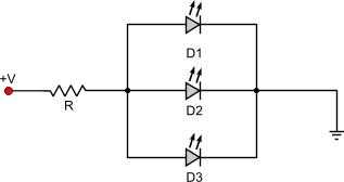
The following rules applies to this connection type: An example: Suppose that we want to light the three LEDs above and the voltage is 24V. Each LED requires 3.6V @ 30mA power to operate. First we calculate the total current needed: ITOTAL = 30 x 3 = 90mA = 0.09 Amperes The current for our calculation is 0.09 Amperes, and the voltage drop is 3.6 volts. By applying this data to the formula given before, we can calculate the resistor: R = (V-VTOTAL) / I => R = (24 - 3.6) / 0.09 => R = 226.6 Ohms Mixed LED connection This is the most complicated situation that could be met when connecting LEDs. With the mixed connection we mean that there can be together series and parallel connection of LEDs in one circuit. All of those LEDs are secured with one resistor and this is the resistor we need to calculate. A mixed LED connection is shown bellow: 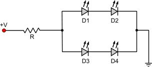
As you may understand this is a rather easy situation and things may get even more complicated. The principals still remain the same though. There is not a standard walk-through to solve this problem as the cases are infinite. There is however an advice that if you follow, it will help you the most. You should first calculate all the LEDs that are connected in series. When this is done, you may work with them as if they were one big LED. This LED is called 'series equivalent'. Then you can go on with the parallel resistors and calculate the parallel equivalent LED. You may continue with this motive until you come to a final series or parallel calculation.In order to calculate the equivalents you should follow the rules:
2. The voltage drop of the series equivalent is the sum of all voltage drops of the LEDs in the series. Simply add all voltage drops to calculate the total voltage drop of the series equivalent.
2. The voltage drop of the parallel equivalent is the same of each one of its items and all of its items should have the same voltage drop. According to this, all LEDs in a parallel equivalent should have for example 3.6 volts, and therefore the parallel equivalent should also have a voltage drop of 3.6 volts. An example: 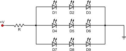
In our circuit above, all LEDs operates under 3.6V @ 30mA and the power supply is 48V. We will try to calculate the protective resistor needed. First we calculate the series equivalent for the LEDs D1-D2-D3, D4-D5-D6 and D7-D8-D9: D1-D2-D3 series equivalent: D123 voltage drop = 3.6 x 3 = 10.8 Volts D123 current = 30mA D4-D5-D6 series equivalent: D456 voltage drop = 3.6 x 3 = 10.8 Volts D456 current = 30mA D7-D8-D9 series equivalent: D789 voltage drop = 3.6 x 3 = 10.8 Volts D789 current = 30mA Now that we have calculate those series equivalents, we could re-write the above circuit as the following: 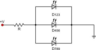
Now we have manage to convert the circuit into a simple parallel connection circuit. Therefore, we could directly calculate the resistor using the parallel LEDs connection calculation above. But we'd rather make one more step for the sake of learning and calculate the parallel equivalent of this circuit. The parallel equivalent would be as follows: DEQ parallel equivalent: DTOTAL voltage drop = 10.8 Volts DTOTAL current = 30 x 3 = 90mA = 0.09 Amperes BR] The circuit now could be re-drawn as follows: 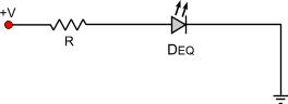
It could not be more easy to calculate. We apply the formula described at the beginning and we calculate the resistor: R = (V - VEQ) / IEQ => R = (48 - 10.8) / 0.09 => R = 413.3 Ohms The above procedure is also known as " Circuit simplification " and using this, you can calculate aach and every kind of LED connection, no matter how complicated it is. LEDs connected on AC voltage Because an LED is a diode, when it is connected to an AC voltage, it will pass only half the waveform. This means that only half of the power supplied will be used to illuminate the LEDs. Therefore, a bridge rectifier should be connected before the LEDs in order to have better results. Moreover, LEDs are designed to work with smooth DC voltage. If they are supplied with a sinewave, even if this is rectified, it still remains a sinewave. It is highly recommended that large capacitors should be connected across the power source so that the waveform is as smooth as possible and the LEDs operate under the best conditions. A simple LED circuit operated with AC voltage would be as follows: 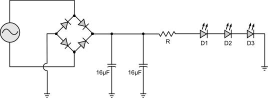
Of course the bridge and the capacitors could be omitted but with this circuit the LEDs will operate more efficiently and for longer time. Relative pages Comments
|
|
 Contact Contact
 Forum
Projects
Experiments
Circuits
Theory
BLOG
PIC Tutorials
Time for Science Forum
Projects
Experiments
Circuits
Theory
BLOG
PIC Tutorials
Time for Science
 RSS RSS
Site design: Giorgos Lazaridis © Copyright 2008 Please read the Terms of services and the Privacy policy |


 Reddit this

