Home     Contact     Projects     Experiments     Circuits     Theory     BLOG     PIC Tutorials     Time for Science     RSS     Terms of services     Privacy policy  
   
 Home      Projects     Experiments     Circuits     Theory     BLOG     PIC Tutorials     Time for Science   

19 June 2011
Author: Giorgos Lazaridis
Manchester and Differential Manchester Code

Manchester coding is a very common data coding method, probably the most common used today. With Manchester coding, we can encode both clock and signal into one, and transmit the signal serially. One distinctive characteristic about this method is that the encoded signal has always an average DC level of 50%. This means that averaging the HIGH and LOW pulse durations of a complete encoded data, will result into 1/2 of the HIGH voltage level. This feature is very helpful in cases where the power output is a function of the data, such as in AM modulation. Using Manchester encoding, the average power is always the same, no matter what data are transmitted. Manchester encoding is also widely used in infrared data transmissions, like for example the Phillips RC protocol.


How Manchester Coding works

Like all other coding methods, Manchester code follows an algorithm to encode data. This algorithm goes like this: The data are represented NOT by logic 1 or 0, but with line transitions. A logic 0 is represented by a transition from HIGH to LOW, and a logic HIGH is represented by a transition from LOW to HIGH. Let's see a very simple 5-bits example:


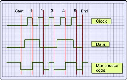
The data to encode is the binary number 10010, reading from left to right. The coding occurs on every falling edge of the clock. On the first falling edge of the clock, the coded signal has a LOW to HIGH transition, because the data is HIGH. On the second falling edge of the clock, the code has a HIGH to LOW transition because the data is LOW. The same algorithm is applied for the rest of the signal.


Manchester Encoding with a microcontroller

The encoding procedure is very simple and straight forward. The following flow diagram shows how to encode data (click to enlarge):


The encoding algorithm is very simple to follow. The microcontroller software is also short and simple to make. No need for extra explanations.


Manchester Decoding with a microcontroller

Manchester code captured from a TV remote control

This is the point where things turn nasty. There are several ways to decode a Manchester code signal. The fact that you have to follow the clock transitions makes it harder to understand. First of all, when decoding Manchester code, you have to know the clock period. Either the clock frequency is known, or it must be found during decoding. Usually, when transmission starts, a start bit and a synchronization bit are sent first for this reason. So from now on, we assume that the frequency of the clock is known. Moreover, we assume that the line is kept HIGH when no transmission occurs, and the line is pulled LOW to start a transmission, exactly as shown in the timing chart on top of this page.

I will explain two methods to decode Manchester code. The first method applies on microcontrollers which have one input pin with edge change detection interrupt. The uC must be able to detect both LOW to HIGH and HIGH to LOW transitions. For example, a PIC microcontroller has such feature on PORTB pins (PORTB INTCON CHANGE). The second method applies to all other microcontrollers, preferable with at least one timer module with interrupt on overflow (but that is not mandatory).


Manchester Decoding with a microcontroller using the Port Edge Detect Interrupt

Here is the flow diagram for this method (click to enlarge):


The Interrupt Service Routine (ISR) is called on every change of the transmission line. On every full clock period (starting from the first HIGH to LOW transition) a level change occurs, and this change "carries" the data bit. If this change is HIGH to LOW, then the bit is 0, else the bit is 1. It is important to keep the interval between changes, because there are cases where the level change does NOT "carry" the data bit. This happens every time that there are 2 similar bits in row. When this happens, the code changes state during the half period of the clock. Notice for example the second and third bits (starting from left) on the example timing chart on top of this page. These data bits are both 0. So, as said before, the Manchester code line will create an extra level change in the middle of the clock pulse. That is why you must know the full clock period during decoding.


Manchester Decoding with a microcontroller using time delay

I think that this method is easier to understand. Here is the block diagram (click to enlarge):


When the first LOW level is detected on the transmission line (which means that the transmission starts), the microcontroller waits for a full clock period to pass. This can be either done with a timer module or with repetitive loops. Then the uC reads the transmission line. If it is HIGH, then the bit received was 1, otherwise it was 0.


The Differential Manchester Coding

The Differential Manchester Code is a variation of the Manchester code. After searching around the internet for a while to find more info about this method, i sadly discovered that although there are many sites explaining the Differential Manchester Code, most of them do not make it very clear. So i had to seek in my books for more info. I then discovered that it is not that hard to understand the differential coding algorithm after all. Let's see an example:


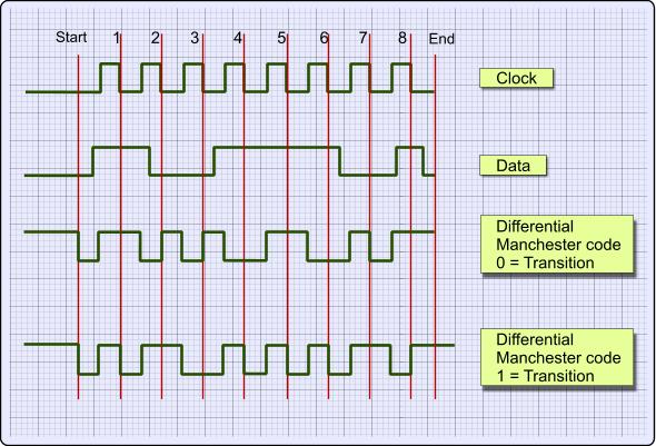
Like before, the transmission line is kept HIGH when no data is sent (before Start and after End). There are 2 encoding methods: The first is the "Transition on LOW" and the second is the "Transition on HIGH". Both methods work exactly the same. For this example i am going to use the first method, "Transition on LOW".

Here is how it goes. In the middle of each clock pulse, a transition occurs, regardless of the bit that was sent or is about to be sent. A data bit is send during each negative clock transition. If the data bit is 0, then a polarity transition occurs (if was HIGH it goes LOW, and if it was LOW it goes HIGH), otherwise the line remains unchanged.

In our example, the data that is transmitted is the binary '10011101' (starting from left to right). Each data bit is transmitted during negative transition of the clock. I have mark these clock transitions with red lines (except the first and last lines which indicate the start and stop of the transition). Between each bit transmission, the code line changes polarity. This is done to help the receiver recreate the clock signal and synchronize with the transmitter. As i said before, i will use the "Transition on LOW" method. This means that when a bit is transmitted, if this bit is ZERO the data line changes polarity. Otherwise, if the bit is 1 the data line polarity remains unchanged.

Suppose now that we want to transmit this byte (10011101). The code line is HIGH. The transmission is initiated by pulling the code line LOW. After half a pulse, the output is pulled HIGH. This is part of the synchronization transition that occurs every middle of a bit transmission. Half a pulse next, the first bit is transmitted. The first bit is 1 (starting from left), so the code line polarity remains unchanged. After half a pulse, the code line polarity changes state and goes LOW. After one full pulse, the second bit is about to be transmitted. This bit is the 0, so the code line changes polarity and goes HIGH. The same algorithm is used to transmit all 8 bits of the data. Finally, the code line is pulled HIGH and the transmission ends.

The major difference between the Differential Manchester Code, is that the receiver does not need to know the polarity of the signal. The polarity can be figured from the line transitions. In the above example, and NOT from the code line polarity. This is something that makes this method kinda difficult to understand. It does not matter whether a logical 1 or 0 is received, but only whether the polarity is the same or is different from the previous value.


Comments

  Name

  Email (shall not be published)

  Website

Notify me of new posts via email


Write your comments below:
BEFORE you post a comment:You are welcome to comment for corrections and suggestions on this page. But if you have questions please use the forum instead to post it. Thank you.


  • At 26 November 2015, 0:32:48 user Indu wrote:   [reply @ Indu]
    • Excellent Explanation. It helped me a lot.


  • At 19 November 2015, 10:46:45 user Abdullah wrote:   [reply @ Abdullah]
    • good, Very good


  • At 23 December 2014, 11:23:23 user abhi wrote:   [reply @ abhi]
    • Fully confusing, better explained on every other website! Especially Wikipedia


  • At 8 July 2014, 7:06:11 user Andrey wrote:   [reply @ Andrey]
    • Thanks a lot!
      I made in such way:

      I use 2 KHz 4 KHz playing from speaker smartphone, notebook, ipad. It received by microphone and STM8L101.
      "0" - long (8) tone 24 KHz, "1"- two short (4) tones 2KHz,4KHz or 4KHz,2KHz

      ///////////////////////////////////////////////////////////////////////////////////////////////////
      Transmitter (J2ME ):

      // "Pilot tone high freq 4 KHz"
      for(int i=0;i<15;i ){d[n ]=0; d[n ]=(byte)255;} (shit! in j2me byte != 0-255)

      // Here code = 01011000 pushed to audio array d[] with audio header (8 KHz mono 8 bit) (omitted)
      // "0 low tone 2 KHz"
      for(int i=0;i<8;i ){d[n ]=0;d[n ]=0; d[n ]=(byte)255;d[n ]=(byte)255;}
      // "1 high-low"
      for(int i=0;i<4;i ){d[n ]=0; d[n ]=(byte)255;}
      for(int i=0;i<4;i ){d[n ]=0;d[n ]=0; d[n ]=(byte)255;d[n ]=(byte)255;}
      // "0 high"
      for(int i=0;i<8;i ){d[n ]=0; d[n ]=(byte)255;}
      // "1 low-high"
      for(int i=0;i<4;i ){d[n ]=0;d[n ]=0; d[n ]=(byte)255;d[n ]=(byte)255;}
      for(int i=0;i<4;i ){d[n ]=0; d[n ]=(byte)255;}
      // "1 low-high"
      for(int i=0;i<4;i ){d[n ]=0;d[n ]=0; d[n ]=(byte)255;d[n ]=(byte)255;}
      for(int i=0;i<4;i ){d[n ]=0; d[n ]=(byte)255;}
      // "0 low"
      for(int i=0;i<8;i ){d[n ]=0;d[n ]=0; d[n ]=(byte)255;d[n ]=(byte)255;}
      // "0 high"
      for(int i=0;i<8;i ){d[n ]=0; d[n ]=(byte)255;}
      // "0 low"
      for(int i=0;i<8;i ){d[n ]=0;d[n ]=0; d[n ]=(byte)255;d[n ]=(byte)255;}

      // "Past high freq"
      for(int i=0;i<15;i ){d[n ]=0; d[n ]=(byte)255;}
      ...
      InputStream stream = new ByteArrayInputStream(d);
      Player player = Manager.createPlayer(stream, "audio/x-wav");// didn't find other method still :-(((
      player.setLoopCount(1);
      player.start();
      // byte is departed!


      ///////////////////////////////////////////////////////////////////////////////////////////////////////////
      Receiver (STM8):

      INTERRUPT_HANDLER(TIM3_Handler, 21)
      {
      TickCounter ;
      //---- lenght semiwave (ticks) frequency of tones ----
      Mic = (GPIOC->IDR & (uint8_t)GPIO_Pin_0); // was changing port? = end semiwave
      if (Mic != Port_old) // it was! so we know length = freq
      {
      if (TickCounter < 15) {Tone=0;} else {Tone=1;} // differ two tones by freq and write 1111 or 000000
      Bods[NTrans] = TickCounter;
      TickCounter=0;
      DlitGudka ; // semiwaves count = length tones
      }
      Port_old = Mic;


      //----- find begin end tones = lenght of tones (9-14, 16-28 %u0438 30-40 of symbols ) ------------
      if (Tone != ToneOld) // end tone = 000000000 change on 111111111 or 11111111 on 0000000
      {
      Trans[NTrans]=DlitGudka; DlitGudka=0; // save lenght tones
      //---------------- collect bits to byte----------------------
      if ((Trans[NTrans]>25) && (ByteIn==0) ) goto end1; // pilot (long tone at the start packet)
      if ((Trans[NTrans]>25) && (ByteIn>0) ) {goto end;} // past (long tone after packet)
      if (Trans[NTrans]>12) { ByteIn <<= 1; ab=0; BitCounter ; goto end;}
      if ((Trans[NTrans]<12) && (ab==0) ){ ab ; goto end; }// receive 1st semi-bit
      if ((Trans[NTrans]<12) && (ab==1) ){ ByteIn <<= 1; ByteIn |= 1; ab=0; BitCounter ; } // receive 2nd semi-bit
      end:
      NTrans ;
      if (BitCounter==8) {bytes[ByteCounter]=ByteIn; ByteCounter ; ByteIn=0; NTrans=0; BitCounter=0;}// byte is received!
      end1: {}
      }
      ToneOld = Tone;
      }

      All working fine! Thanks a lot Brent!!!


  • At 2 July 2014, 21:11:46 user Brent Fisher wrote:   [reply @ Brent Fisher]
    • With differential Manchester encoding, one type of bit is twice the frequency of the other type of bit, in your example being that zeros have twice the frequency of ones. To decode it you need to keep track of how recently there's been a transition, and in your case if it has been really recent then a zero has been transmitted. Here's a simple C function that does that...

      unsigned char manchester_demod(signed short capacitor_sample, signed short threshold,double xdimension,unsigned char resetit)
      {
      unsigned char retvalue=2;
      static int waitcounter=0;
      static int transcount=0;
      static unsigned char code=0;
      static signed short old_sample=0;
      static double newx=0;
      if(resetit==1)
      {
      newx=xdimension;
      }
      waitcounter ;
      if((capacitor_sample >= threshold && old_sample < threshold)||(capacitor_sample < (-threshold) && old_sample >= (-threshold)))
      {
      float frequency=waitcounter/(newx);
      code=3;
      if(frequency >= 1.5 && frequency < 2.5)
      {
      code=1;
      if(frequency > 1.74 && frequency < 2.25)
      {
      newx=waitcounter / 2.0;
      }
      }
      if(frequency < 1.5 && frequency > 0.333)
      {
      code=0;
      if(frequency > 0.874 && frequency < 1.125)
      {
      newx=waitcounter;
      }
      }
      waitcounter=0;
      if(code!=3)
      {
      transcount ;
      if(transcount > (!code))
      {
      retvalue=code;

      transcount=0;
      }
      }
      else
      {
      transcount=0;
      }
      }
      old_sample=capacitor_sample;
      return retvalue;
      }

      Send the waveshape as 16 bit audio samples into 'capacitor_sample' set threshold to 128 and the xdimension to the amount of samples between the fastest transitions. You get out bits from the return value each time it is '0' or '1'.


  • At 21 December 2013, 14:47:19 user Andrey wrote:   [reply @ Andrey]
    • Dear Giorgos!

      As You are profi in it, explain me please, why sometimes they wrote:

      "Differential Manchester encoding is not to be confused with biphase mark code (BMC) or FM1, " (http://en.wikipedia.org/wiki/Differential_Manchester_encoding , http://www.digplanet.com/wiki/Differential_Manchester_encoding ),

      while mostly they wrote:

      "Differential Manchester encoding, also called biphase mark code (BMC) or FM1" (http://en.wikibooks.org/wiki/Communication_Systems/Line_Codes#Differential_Manchester ) ?


  • At 12 September 2013, 17:36:39 user Giorgos Lazaridis wrote:   [reply @ Giorgos Lazaridis]
    • @Richard Yes that would be different


  • At 12 September 2013, 17:00:01 user Richard wrote:   [reply @ Richard]
    • If an RF receiver collects your sample byte (10011101) and outputs an encoded stream to RS232; what would the data stream look like in 0's and 1's in differential encoding? ( I am assuming a RF receiver would use differential). I would be expecting 16 bits. Thanks


  • At 15 May 2013, 1:54:49 user Rohit wrote:   [reply @ Rohit]
    • nice explaination pal..
      but its hard for me to get the concept "how to code the differential coding" in simple terms.. could anyone help me with this.., my semester exams are very near...


  • At 27 November 2012, 11:48:39 user Ribice wrote:   [reply @ Ribice]
    • Very great and clear explanation. I've used some of the statements in my lab report, thank you :)


  • At 16 September 2012, 9:06:14 user kiranvarma-npeducations wrote:   [reply @ kiranvarma-npeducations]
    • That was a very neat and clean explanation! thanks Giorgos Lazaridis. You just awesome! You cleared all my doubts regarding digital coding mechanism with this tutorial.


  • At 12 September 2012, 2:15:04 user pant wrote:   [reply @ pant]
    • that,s better......


    delicious
    digg
    reddit this Reddit this
    Faves


     HOT in heaven!


    NEW in heaven!


    New Theory: AC electric motor working principle


     Contact     Forum     Projects     Experiments     Circuits     Theory     BLOG     PIC Tutorials     Time for Science     RSS   

    Site design: Giorgos Lazaridis
    © Copyright 2008
    Please read the Terms of services and the Privacy policy