
|
 Home Home
 Projects Projects
 Experiments Experiments
 Circuits Circuits
 Theory Theory
 BLOG BLOG
 PIC Tutorials PIC Tutorials
 Time for Science Time for Science
|
| ||
|
5 April 2011 Author: kammenos The CharlieplexingHistory Charlieplexing is a rather new multiplexing technique. It was first proposed in early 1995 by Charlie Allen at Maxim Integrated Products for driving a multiplexed display. Like other multiplexing techniques (eg matrix), charlieplexing is used to control more loads with less I/O ports. Charlieplexing does more! A typical I/O port of a microcontroller, when used as an output, has basically two states: the HIGH and the LOW state. When the port is used as an input, it is driven into High Impedance state. During this state, the port's internal resistance gets very high values (Mega Ohm), and the current that flows through the port is very small, measured in micro amperes. Charlieplexing can multiplex the I/O ports of a microcontroller more efficiently, because it utilizes this characteristic, which is called "tri-state". A very simple example Look at the following simple circuit, which uses two ports to control two LEDs. 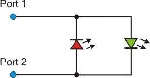
Here is the principle of operation. The two LEDs are connected anti-parallel, the anode of the red LED (left) is connected to the cathode of the green LED (right). When port 1 becomes HIGH and port 2 becomes LOW, then the green LED turns on, and when port 1 becomes LOW and port 2 becomes HIGH, the red LED turns on. One more port... Now we add one more port to control more LEDs. I have broken apart the circuit into 3 sub-circuits, each one showing 2 ports. So, we have 2 LEDs controlled by port 1 and 2, two more LEDs controlled by ports 1 and 3, and another 2 LEDs controlled by ports 2 and 3, a total of 6 LEDs: 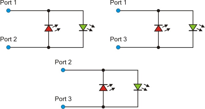
So, with the same principle as before, a microcontroller can control individually 6 LEDs with only 3 ports. A typical matrix cannot control that much LEDs with only 3 ports! As i said before, the charlieplexing utilizes the tri-state of a micro-controller's port. But how? Let me re-draw the same circuit with the 3 ports and the 6 LEDs, but this time i will not draw them separately: 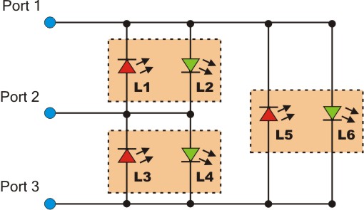
When Port 1 is HIGH and Port 3 is LOW, then L6 will light. But in what state must Port 2 be? If Port 2 is HIGH, then L4 will light as well, and if it was LOW, L2 would light simultaneously. So, to avoid unwanted situations, Port 2 must be in High impedance state, often show with the symbol "Z". Same applies of course if we try to light L2. Port 1 should become HIGH and Port 2 should become LOW. If Port 3 was HIGH, L3 would light as well, and if it was LOW, L6 would light simultaneously. So, the general rule is that, only 2 ports can be simultaneously outputs and all others are in High Impedance state by defining them as inputs. Operation Table So, here is the Operation Table for the previous circuit. Symbol H stands for HIGH, L for LOW and Z for High Impedance:
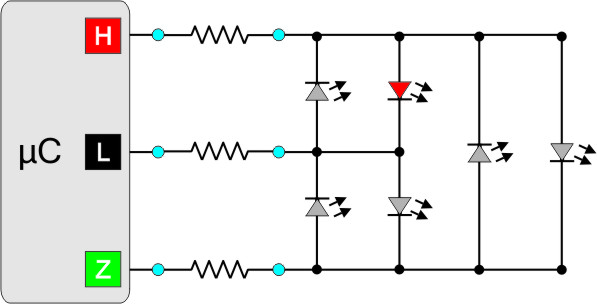
Many LEDs, but how many? You can calculate the maximum number of LEDs that can be controlled with Charlieplexing, if you solve the following formula: n = Pn x (Pn-1) n is the number of LEDs and Pn the number of ports used by the microcontroller. So, for 3 ports you can control 3 x (3-1) = 6 LEDs, for 4 ports 4 x (4-1) = 12 etc. Do you see something strange??? Suppose that we want to light L6: According to the previous table, Port 1 must be High and Port 3 Low, with Port 2 driven to High Impedance. L6 if forward biased and it will light, correct, but what about L2 and L4? They are both forward biased! They should both light, shouldn't they? The answer is simple, but you need to know something about LEDs. LEDs have a very narrow voltage operation range. They may consume very little current, but they will not light if the voltage across them is bellow a specific value. Typically, LEDs operate from 2.9 to 3.3 volts (but that is not a standard range). So, if we give +3.3 volts to Port 1 and 0 volts to port 3, then L6 will be forward biased with 3.3 volts and it will light indeed. But L2 and L4 are in series, and -according to Kirchhoff- the total voltage drop across a series circuit is the sum of the voltage drops across each part. In other words, the series circuit is composed by 2 parts, L2 and L4. So, each of these parts will have 3.3/2 volts across it's leads, which is 1.65 volts, way bellow the minimum operational voltage threshold. So, these two LEDs will NOT light because they do not have sufficient voltage across them. Moreover, the current through L2 and L4 will be very small, a couple of miliamps or less. Where to connect the limiting resistors? Typically, the correct point to connect your limiting resistors is between the microcontroller and the ports of the Charlieplexing circuit. Each resistor must have HALF the value of the required value. If for example you want to protect the LEDs with 200 Ohms resistor, then you must use 100 ohms resistors, and that is because, to light each LED, the current goes every time through 2 resistors, and not one. Here is a typical circuit: 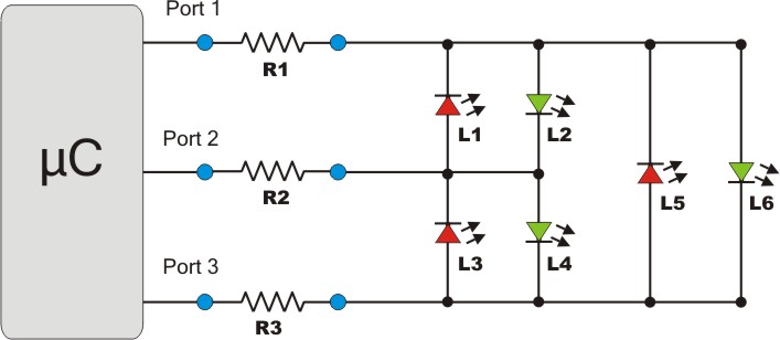
This circuit will operate normally, and all LEDs will have the same brightness. I said before, that only two ports can be outputs simultaneously. But that is not absolutely true. There are special situations, where more than 2 ports can be outputs, so that more than one LED is turned on. This can only happen with LEDs that have a common anode or a cathode, like for example L6 and L4 or L1 and L5. These LEDs can light simultaneously. Take for example L4 and L6. If Port 1 and Port 2 are HIGH and Port 3 is LOW, L4 and L6 will turn on. But the problem is that they will have much less brightness than the other LEDs. Why? The answer is again simple. Suppose that each resistor is 100 ohms and the voltage supplied by the microcontroller is 5 volts. If ONE LED is turned on, then the maximum current allowed can be calculated by the ohm's law as follows: I = V / R => I = 5 / (100+100) => I = 25mAmps 25 mAmps can go through the LED. But when 2 LEDs light simultaneously, the current is divided by two for each LED, because the LEDs are connected in parallel. So, only 12.5 mAmps can go through each LED, and this means that these LEDs will not be as bright. There is a solution though. The solution is to connect one resistor for each LED, like this: 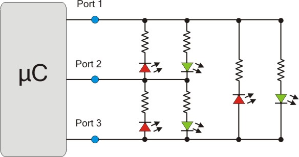
Now each LED has its own resistor, and the current is no longer divided if other LEDs light simultaneously. So, the first circuit with the 3 resistors works pretty well, only if you plan to light each LED alone. If (for some reason) you want to light more than one LED simultaneously, then you need to follow the second circuit with one resistor for each LED. In general, the second circuit is rarely used and i suggest you avoid it unless you have a very good reason. And don't worry, there is another way to light more than one LED simultaneously... So what? Only one LED can be turned on? Yes and No. Yes because as i explained before, the Charlieplexing cannot control more than one LED at a time (i am always talking about the first circuit with the 3 resistors). And no because, the human eye can be tricked :D Suppose that you want to light L1 L2 and L3 simultaneously. The only thing that you need to do, is to turn on L1, then turn it off, turn on L2 and turn it off and then turn on L3 and turn it off as well, but all this in a short time and continuously. If the ON-OFF of the LEDs is fast enough, the human eye cannot detect it. It is the same principle like in a cinema movies. The pictures change so fast, that the human eye thinks it is a continuous film. There are some limitations and parameters that you need to take into account. First of all, the ON-OFF rate of an LED must be fast enough for the eye to be tricked. If for example the rate is 10Hz, the flickering will be visible. So, choose a frequency above 24Hz - remember that 24 frames per second is an acceptable movie frame rate. Another problem that may appear is the brightness. The LEDs will not turn on at full brightness, and that is because the circuit will operate as a PWM dimmer for each LED, taking into consideration that there is an OFF time. This OFF time has to do with the number of LEDs that have to be controlled. The more the LEDs, the longer the OFF time for each LED, and thus the less the brightness. There is though one solution for this problem. You may choose to use smaller resistors than the calculated. This way, more current will flow within each LED and thus it will be brighter. Be careful though! You don't want to go much above the nominal LED current allowed for two main reasons. First, the lifespan of the LED will be reduced. You may not notice the over-current situation by the brightness (because of the PWM effect), but this over current will certainly reduce the lifespan of the LED. And second, if the current is much too high above the nominal forward LED current and the microcontroller crashes for some reason, then the LED that is currently turned on will have a very hard time, for it will remain ON with full current flowing... Charlieplexing also to interface buttons Same as the classic matrix, the Charlieplexing technique can be used to interface buttons to a microcontroller. Here is a typical circuit to interface 6 buttons with only 3 microcontroller inputs: 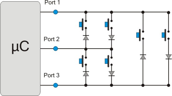
The efficiency is unmatched. With 6 inputs, using the classic matrix method, up to 3x3=9 buttons can be interfaced, but with the Charlieplexing, a maximum of 6x(6-1)=30 buttons can be interfaced. To determine which button is pressed, the microcontroller must run a loop through all inputs. Each time, only one pin is defined as output and all others as inputs. Te inputs must be pulled HIGH or LOW. If the microcontroller supports internal pull-up resistors, then they can be used to minimize external components. If the inputs are pulled-down, then the output pin is driven HIGH. The microcontroller then checks all inputs. If an input is found HIGH, then this means that a button is pressed. Each button corresponds to a specific Output-Input pair. Look at the following animation: 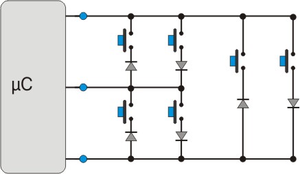
This method has disadvantages and permanent ghosts First if all, the diodes are mandatory for the circuit to operate normally. This makes the overall use more complex. But the most basic disadvantage it the ghosting. I have explained what the ghosting and masking problems are in the matrix theory, and i will not go through it again. Ghosting can also occur in the Charlieplexing method. In matrices, the ghosting can be solved by adding diodes to the buttons to prevent back current flow. But in charlieplexing, ghosting cannot be solved. That is one good reason, why charlieplexing is not widely used, although it is so efficient. But still, it can be used in cases where only one button is pressed at a time. If for example you make a through-feed machine with multiple limit switches one after the other, you can safely use charlieplexing to interface them, as long as only one limit switch is activated at a time. Comments
|
|
 Contact Contact
 Forum Forum
 Projects Projects
 Experiments Experiments
 Circuits Circuits
 Theory Theory
 BLOG BLOG
 PIC Tutorials PIC Tutorials
 Time for Science Time for Science
 RSS RSS
Site design: Giorgos Lazaridis © Copyright 2008 Please read the Terms of services and the Privacy policy |