|
 Home Home
 Projects Projects
 Experiments Experiments
 Circuits Circuits
 Theory Theory
 BLOG BLOG
 PIC Tutorials PIC Tutorials
 Time for Science Time for Science
|
| ||
|
29 December 2010 Author: Giorgos Lazaridis Reverse-Engineering the Linear Guide of a DVD HeadMost of the times, research comes from the need. This time, i needed a linear guide with a good precision, for a project that i plan to make. I began searching my scrap boxes and my museum, and did found some solutions. But the most simple and effective, was hidden in my -very- old CD (or DVD) player (or recorder). All DVD recorders have their head (laser diode, receiver and some other gizmos) mounted on a carriage, able to travel linear on rails with great precision, radially in respect to the CD. One motor is used to move this carriage. This system is exactly what i need for my coil winding project (not ready yet). Guts out So, lets begin. First i need the victim. In my museum i have ten or fifteen old DVD players. So i chose one (randomly) and opened it. This is what i found inside (most probably many of you have done this before, don't you???):
From now on, i use super small screw drivers, philips and torx type. The head hides a small treasure: After an hour or so, i finally got in my hands the lightened mechanism that i am about to use.
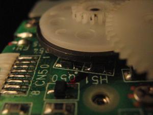
The moving mechanism The mechanical part of the mechanism is straight-forward. A motor moves a gear with approximately 2.14 reduction ratio, and then it moves another gear with another 3.2 reduction ratio, and then moves the last gear with 1.14 increment. The final gear has 21mm diameter, and it converts the rotational move into linear. The calculations are now easy to make. Reverse engineering the PCB was kinda harder though, because i had absolutely nothing in my hands, not a part number, no nothing. Reverse engineering the PCB In a first glance, i only could recognize the motor type. Only two wires comes out of it and goes to a + and - connector. I bet that this is a brushed DC motor. Then i noticed something strange on the first gear, the one that is directly mounted on the motor. A black disk that looked like rubber was on the perimeter. But hey, what does a rubber on the gear??? Maybe it is not a rubber. It could be a magnet...:
I was not surprised to find out that this is a magnet, and i was not going to be surprised, if there were Hall sensors around there. After all, the magnet-Hall sensor pair is frequently used in many applications, like in this liquid flow sensor, in which a Hall sensor is used to detect two magnets. So, i looked closer and... hmmmmmmmm, what are these under the disk? 
At that point, i had to remove the motor and the PCB form the case to work easier. And so i did...
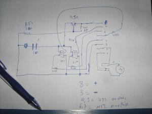
It looks easy, but it was not that easy at all. There were tracks going under the SMDs, and also, as you notice, none of the SMDs -except the resistors and the capacitors- had clear markings to identify them. The two big SMDs under the disk, could be Hall sensors, yet i was not sure. I only suspected it. Also, the name of these parts encouraged me to this thought (H50 and H51). Maybe H comes from Hall... So, slowly and carefully, i made a schematic on paper with these photos. This is a technique that i have not used before, but i plan to use it again in the future. I do not know how good it will work with double sided PCBs, works sweet for single sided like this. Here is the schematic. 
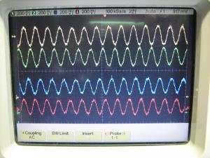
And now comes another wild guess. If these parts are indeed Hall sensors, then they should have a positive and a negative supply. So, two of their pads should be connected together. And indeed, if you notice the schematic, there are 2 pads connected together. Actually, these are the only pads of these SMDs that are connected together. Then, i had to identify which of these two is the positive. Luckily, near by, a capacitor was to save the day. It had the name C50, which means capacitor, and it had also a mark (like the ones on the diodes) which marks the positive lead, probably is a tantalum capacitor. Following this line, i found the positive trace, and thus the other is the negative! That simple. It was time to identify all the connector pads. I had the positive which was pin #8, the negative is pin #3, the motor is connected to pin #1 and #2. There are 4 more pins waiting to be identified. From the schematic, these goes through 470 Ohms resistors to the 2 SMDs that i suspect they are Hall sensors. So, i consider them as outputs... The oscilloscope will reveal the bare truth Before i connect the PCB to the oscilloscope, i first had to solder wires to the pads. That was really not easy. The pads were too close one each other, and i had to be super careful to avoid short circuits Isn't it great when things just work? The 4 channels of the oscilloscope shows the outputs of 4 Halls sensors, they ARE Hall sensors after all. Take a closer look: 
The yellow and green channel comes from the first Hall sensor, and the other two from the second. The End So, now, i do know what type of motor is. I do know the reduction ration for all gears. I do know what each pin of the PCB does. I will make a PWM controller for the motor, and a couple of Schmidt Triggers for the Hall sensors, and the control of this cool linear guide will be in my hands. I suggest you save your old DVD drives, because one day you may need them! Comments
|
|
 Contact Contact
 Forum Forum
 Projects Projects
 Experiments Experiments
 Circuits Circuits
 Theory Theory
 BLOG BLOG
 PIC Tutorials PIC Tutorials
 Time for Science Time for Science
 RSS RSS
Site design: Giorgos Lazaridis © Copyright 2008 Please read the Terms of services and the Privacy policy |