|
 Home Home
 Projects Projects
 Experiments Experiments
 Circuits Circuits
 Theory Theory
 BLOG BLOG
 PIC Tutorials PIC Tutorials
 Time for Science Time for Science
|
| ||
|
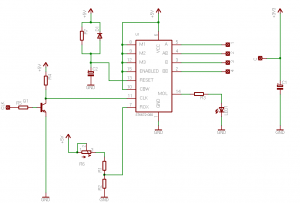
2 August 2010 Author: Giorgos Lazaridis A Microstepping Driver with the Sanyo STK672-080A few weeks ago, i had the extreme luck to get an old color photo-copy machine for my chopshop. Except some problems that it had with the heater, it worked perfectly fine. Yet, the company that owned this machine wanted to get rid of it, and as i was kinda "passing by the neighbor", i picked it up for free! The top side of the machine had 5 stepper motors, each one different, but all had 200 steps per cycle. Quickly i removed all the useful parts from the machine, and then i started fooling around with the steppers. I made a couple of controllers (that i may present later), some with a PIC and others without microcontroller. A few days later, i took a more "scientific" look on the PCBs that i had carefully removed, and more specific on the one that the 4 steppers where connected to. And then i noticed two parts with the number STK672-110 and another two with the number STK672-080. I googled for the second one, and the first result was "Stepping Motor Driver (Sine Wave Drive) Output Current: 2.8 A (No Heat Sink*)"!!! Within a few minutes, i had the soldering iron hot and ready for removing the stepper motor controllers from the PCB! The circuit Following the instructions from within the STK672 080 datasheet, i present you the micro-stepping circuit schematic: 
Hopefully you will agree with me: The circuit is ridiculously simple for what it does! If you are not quite familiar with the stepper motors and the micro-stepping excitation itself, then i would suggest that you read the stepper motor theory first, and then you will understand what i mean. This hybrid chip requires only a clock input to operate as a microstepping controller! The frequency of this signal will eventually determine the speed of the rotation. Moreover, this hybrid chip can change the rotation direction of the motor with a single wire! If the input CBW (pin 10) is 1, then the motor rotates clockwise, otherwise if this input is 0 it rotates counterclockwise! No other circuitry required! The "ENABLED" pin will enable or disable the controller. If the pin is held HIGH (1), the controller operates normally, while if held LOW (0), the controller will be deactivated. At this point i should mention that if the controller is deactivated, the motor is NOT powered, and thus the shaft can be rotated freely, only by overcoming the detent torque. For the motor to maintain the full breaking torque while not rotating, the controller must NOT me deactivated. Instead, you should better stop the clock pulses. This way the motor will be stopped with full break torque. As far as the clock input is concerned, i use my homemade function generator to provide the pulses. You can use instead any other oscillator circuit - with respect to the maximum frequency input of the chip (50 KHz). For example, a simple 555 astable multivibrator will do just fine, or even a very simple transistor oscillator. I use a NPN transistor to interface the clock signal pulses. Finally, the RoX Input. This input must be between 0 and VCC/2 Volts, in our case 0 to 2.5 Volts. R2 is recommended from the manufacturer to be 100 ohms. The voltage on this pin has an effect when the chip uses micro stepping to control the motor (as in our case). I have add a potentiometer (R6) to set the voltage according to your motor. To do this, you should run the motor in very low speed -about 1 revolution per 5 seconds- and change the potentiometer until you get full torque on the shaft, but without step-loosing. The motor must run smoothly with minimum vibrations, in low as well as in high speeds. The large capacitor C1 on the circuit is very important! Without this capacitor, the circuit will NOT work and the controller will overheat very fast! The motor that i use runs at 3.3 volts and draws 2 amperes. This particular controller can control up to 45 volts @ 2.8 amperes. The motor must be -of course- a unipolar 2-phase motor. The connectors 1 through 4 are connected to the coil edges, while the connector C goes to the middle of the coils. A unipolar 2-phase stepper motor has 5 or 6 wires. 4 wires comes from the beginning and the ending of the two coils. There are also 2 more wires from the middle of the coils. Some unipolar motors have these two wires interconnected -and thus have 5 wires at the output-, while others have these 2 wires directly at the output thus having 6 wires. It is just the same! In the second case with the 6 wires, do not forget to connect both the middle (common) wires to the connector C. Even more capabilities! There are 3 more pins to discuss. The M1 through M3 inputs. This controller supports 5 different excitation methods for the coils, full step, half step and 3 more microstepping excitations. If you read the datasheet of this chip, it has a complete explanation of the excitation modes and the pin configuration. So, this chip is even more powerful! Bill Of Materials Relative pages Comments
|
|
 Contact Contact
 Forum Forum
 Projects Projects
 Experiments Experiments
 Circuits Circuits
 Theory Theory
 BLOG BLOG
 PIC Tutorials PIC Tutorials
 Time for Science Time for Science
 RSS RSS
Site design: Giorgos Lazaridis © Copyright 2008 Please read the Terms of services and the Privacy policy |