
|
 Home Home
 Projects Projects
 Experiments Experiments
 Circuits Circuits
 Theory Theory
 BLOG BLOG
 PIC Tutorials PIC Tutorials
 Time for Science Time for Science
|
| ||
|
27 April 2010 Author: Giorgos Lazaridis Closed Loop high frequency PWM PC Fan ControllerThis circuit is the natural evolution of the previous High Frequency PWM Fan Controller and the PIC 3-Wire Fan RPM Controller. In a first glance, the circuit appears to control the duty cycle of high frequency PWM pulses with a potentiometer. Yet this is not the actual operation of this circuit. The Circuit I use a 4-wire fan and i do not need an external switching component such as a MOSFET. Therefore, the circuit is minimal. An 8-pin PIC, a trimmer, the potentiometer and a couple of resistors is everything it needs. Maybe an .1uF capacitor across the power supply (as always) would be useful. Here is the schematic diagram: 
The potentiometer R3 sends the control voltage level to the PIC's A/D converter. The R2 sets the minimum voltage that can be adjusted by the R3 - as you will see later on, this is the maximum rpm setting. The RPM feedback from the fan tacho comes in the GP5 input of the PIC, with a pull-up resistor as required. GP2 generates the PWM pulses (this is the CCP1 output of the PIC). The PWM pulses are driven to the fan control wire directly. A Pull-up resistor is used in the case that the PIC fails. The operation  The circuit mounted on a breadboard for test-run The operation is a little bit more complicated as it looks. The potentiometer will set the control voltage level. This voltage is translated into a binary number. Unlike the High Frequency PWM Fan Controller that will use this number to set the PWM duty cycle, in this circuit the PIC will use this number as an RPM reference point. Then, from the rpm feedback of the fan, the PIC will read the current rotation speed. According to the position of the potentiometer, it will increase or decrease the PWM duty cycle accordingly, so that the fan speed is matched to the potentiometer value! In other words, the potentiometer sets directly an RPM value that we want the fan to rotate with. What is the point to this? Well, as we all know, if a fan is powered with PWM pulses of constant duty cycle, it will gradually tend to decrease its rotation speed, mainly due to dust. If for example a fan runs at 800rpm with 40% duty cycle, after one month of operation, it will run with 700rpm at 40% duty cycle! This circuit, will adjust the duty cycle all the time, so that the rpm are steady! I have set the sampling rate to 250 mSec. This is a rather fast reaction. I did this on purpose, because i want the operator to 'feel' the rpm change when rotating the potentiometer. But the fan usually changes the speed rather slow. Thus, in a large change, the fan will overspeed (if the change is from lower rpm to higher rpm). It will run a few setup cycles before it is centered. This is shown in the following graph. The operator changes the speed from 800rpm to 1300rpm. The fan overspeeds and after a few ups and downs, it is centered to the required speed. 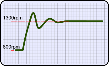
Adjusting the circuit The minimum speed of the fan is fixed, and this is around 450rpm. To change this, you need to mess with the code. The only thing to adjust is the maximum speed - because not all fans have the same maximum speed. The maximum speed can be adjusted with the R2 resistor. Here is how to do it: First of all, set R2 somewhere in the middle. Then, rotate R3 so that the fan rotates at full speed. Most probably, that will NOT be the fan's max speed. Instead, that will be the max speed that is currently set by the R2! Do not worry, all you need to do right now is to rotate R3 completely to the direction that the fan runs faster. Now you need to be smooth and gentle. Slowly turn R2. you will notice that the speed of the fan is changing. Find the direction that the fan rotates faster. Keep rotating to this direction. There will be a point that the fan does not run any faster. This is the point that you need to find. You may use a contactless speed-meter or an oscilloscope to find this position. Or, you can simply put a piece of paper against the fins of the fan to hear noise. You do not need to be very accurate after all. Here is another idea. Suppose that you have a noisy fan with nominal speed 3200rpm. But you never run this fun at that speed. You can then follow the previous steps and adjust R2 NOT at full speed, but at the speed you wish to have as full. For example you can set it at about 2400rpm. If you do so, you have just extend the range of the potentiometer. The potentiometer will now control the fan from 450rpm to 2400rpm! The Program Here is the full assembly listing, if you wish to change and re-compile the code:
If you only want to upload the program as-is, then download this file:
There are 3 parameters (constants) that you may wish to change: You should keep in mind that the above parameter values does NOT correspond to a number %. For example, 40 does not mean 40%. There is an algorithm that calculates the duty cycle. The whole calculation can be found in the datasheet of the PIC (look the Bill Of Materials bellow). The GLMaxDC GLMinDC values are used as limits. The PIC is allowed to change the duty cycle only within the range GLMinDC <= DutyCycle <= GLMaxDC. Be very careful if you change these values, as the fan may stall or the program may malfunction. Bill Of Materials (Second circuit)
Relative pages Comments
|
| |||||||||||||||||||||||||||||||||||||||
 Contact Contact
 Forum
Projects
Experiments
Circuits
Theory
BLOG
PIC Tutorials
Time for Science Forum
Projects
Experiments
Circuits
Theory
BLOG
PIC Tutorials
Time for Science
 RSS RSS
Site design: Giorgos Lazaridis © Copyright 2008 Please read the Terms of services and the Privacy policy |
 Closed loop fan controller - Assembly listing


 Reddit this

