|
 Home Home
 Projects Projects
 Experiments Experiments
 Circuits Circuits
 Theory Theory
 BLOG BLOG
 PIC Tutorials PIC Tutorials
 Time for Science Time for Science
|
| ||
|
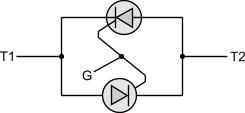
9 April 2009 Author: Giorgos Lazaridis The TriacWhat is a TRIAC The name TRIAC comes from the words TRIode for Alternating Current. The TRIAC was discovered the time that SCR was discovered therefore those two elements have the same history. It is actually composed of two different SCRs connected in parallel and in opposite direction. The formal name of a TRIAC is bidirectional triode thyristor. The name itselfe indicates that a TRIAC can allow current to flow within it's leads in any direction. This makes a TRIAC more suitable than an SCR when AC voltage needs to be controlled. As mentioned before, a TRIAC is actually two SCRs connected in parallel and opposite. The electronic symbol of a TRIAC is as follows: 
And the equivalent circuit of a TRIAC using two SCRs is: 
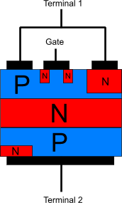
The PNP layers of a TRIAC are as follows: 
The theory of operation for a TRIAC is based on the theory of operation of an SCR triode. The differences between those two elements are: The TRIAC has no Anode or Cathode pin that needs to be connected reverse of forward in order to allow current to flow within the device. Once a pulse is applied to the gate of the TRIAC, it shall become conductive and shall allow current to flow from the bias no matter what polarity. Someone would expect the TRIAC to become conductive with positive pulses. This is far from true. A TRIAC becomes conductive with bot positive or negative pulses. As mentioned in the previous point, it has no polarity and therefore the polarity off the pulse on the gate is irrelevant. It only needs to be greater than the gate threshold voltage to turn on the TRIAC. As it is already known from the theory of operation for the SCRs, an SCR goes into a non-conductive state when the the voltage difference between the anode and the cathode of the SCR is equal or smaller than zero volts. TRIACs goes off (non-conductive) only when the voltage between the two leads is zero volts You can find a complete theory of operation for the SCRs in this page. Applications TRIACs are used in many applications such as light dimmers, speed controls for electric fans and other electric motors, and in the modern computerized control circuits of many household small and major appliances. They can be used both into AC and DC circuits but the original design was to replace the use of two SCRs in AC circuits. TRIACS may not turn on reliably with non-resistive loads, because due to the phase shift the holding current may not be achievable at trigger time. Therefore, a pulse train is sent to the gate until the load is turned on. Because of the fact that the gate current does not need to be maintained throughout the entire conduction angle, current can be limited significantly and this is a benefit when drive capabilities are narrow. Relative pages Comments
|
|
 Contact Contact
 Forum Forum
 Projects Projects
 Experiments Experiments
 Circuits Circuits
 Theory Theory
 BLOG BLOG
 PIC Tutorials PIC Tutorials
 Time for Science Time for Science
 RSS RSS
Site design: Giorgos Lazaridis © Copyright 2008 Please read the Terms of services and the Privacy policy |