A very simple thermocouple wire. One wire is made of Chromium and the other of Aluminum. Both are Nickel alloys.
In 1821 Thomas Johann Seebeck (1770-1831) noticed that, if two wires from different material are connected at their endings performing two different junctions, and these junctions do not have the same temperature, then placing these wires near by a compass, would cause the compass to move. At first he believed that the temperature is the reason to change the magnetic field. Later on, he understood that a current was flowing within the wires that generated a magnetic field and moved the compass. That called the Seebeck Effect
The Seebeck Effect is one of the three thermoelectric phenomena and the first to be discovered. Along with the Peltier effect and the Thomson effect, it explains how the temperature difference can create a voltage.
The Seebeck effect is present whenever two dissimilar metals -of any material- performs a junction. Nevertheless, there are some metal pairs that have a predictable voltage according to temperature, and have also larger temperature gradients. These pairs are named with a letter, as for example the type-E thermocouple. The most popular type of thermocouple is the type-K. This type is made of Nickel-Chromium versus Nickel-Aluminum wires and has a very wide range of temperature gradients (from -200oC up to 1300oC) where the voltage changes almost linear.
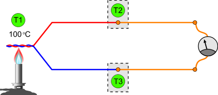
The following drawing demonstrated a thermocouple. The left junction is heated. The right junction is kept at room temperature. Thus, a current flows within the wires:
As someone would expect, if the right junction does not exists, a voltage difference shall be created across the wire endings:
The three Thermo-Electric Laws
There are three empirical Thermo-Electric Laws to explain the operation of the thermocouple:
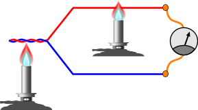
1. The Law of Homogeneous CircuitsAn electric current cannot be sustained in a circuit of a single homogeneous metal
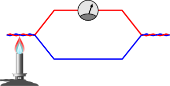
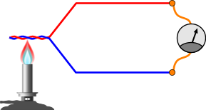
Look at the two following images. The two circuits are identical and the temperature in the junction is equal. Both will generate a voltage difference. On the right circuit, a second heater is placed under one of the two thermocouple wires and heat it up. The first law states that, because the second heater heats ONLY one wire and NOT the junction, the output voltage of both circuit will be the same. The output voltage is only affected by the junction temperature and not the temperature of the wires. That is because, any temperature change to a homogeneous wire will create no voltage.
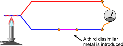
2. The Law of Intermediate MetalsIf two dissimilar metals performs a thermocouple, and a third dissimilar metal is introduced to the circuit, as long as the temperature along the entire length of the third metal is kept uniform, the output voltage will NOT be affected
Look at the following circuit. The blue wire of the thermocouple is joined with a third dissimilar metal. If the temperature of this wire across it's entire length is the same, then the output voltage will NOT be affected by this insert.
3. The Law of Intermediate TemperaturesIf a thermocouple with 2 junctions with temperatures T1 and T2 produces a voltage difference V1, and voltage difference of V2 in temperatures T2 and T3, then voltage generated when the temperatures are T1 and T3 will be V1+V2.
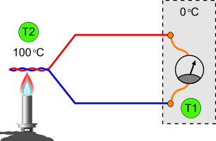
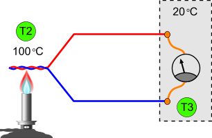
This law is very important to understand how to acquire the temperature from a thermocouple. Usually, the temperature to voltage characteristic of a thermocouple (as you will see later on) is given for 0oC (32oF) reference temperature. Look at the following 2 circuits. The thermocouple is a K-type thermocouple, and the voltmeter uses copper wires. At the point that the voltmeter is connected to measure the voltage, two new thermocouple junctions are created! This is a major problem of thermocouples and will be discussed in details later on. At the left circuit, these new junctions are kept into 0oC (32oF). This way, the measured voltage can be directly converted into temperature, as the table to convert it is usually with reference temperature 0oC. But in real life, the reference temperature is not 0oC. Looking at the right circuit you can see a more realistic example. The reference temperature now it 20oC. The voltage cannot be directly converted into temperature as the reference junction (where the voltmeter is connected) is not at 0oc. According to the 3rd law, if we know the reference temperature, then we can calculate the measured temperature, by adding the measured voltage and another voltage named VREF. This VREF is the voltage that would be created by the thermocouple, if the non-zero reference voltage was measured by a thermocouple junction with reference temperature 0oC. I know it is complicated. Frankly, it is not!
Compensating the reference temperature
An example: For the left circuit, suppose that T1 = 0oc (first reference temperature). According to the measured voltage, we can directly convert to temperature for T2. In our example, for a K-type thermocouple, the measured voltage would be 4.095mV, that corresponds to 100oC. But a measuring instrument is rarely placed in 0oC. On the second circuit (right side), the measuring instrument is placed in a room with 20oC. Although the temperature T2 is still 100oC, the measured voltage will be now 3.297 mV! Why? Because the junctions where the voltmeter is connected is NOT in 0oC, thus they introduce another opposite current to the circuit!
To calculate the T2, we need to compensate T3! According to the 3rd law, we need to add to the measured voltage, the voltage that would be generated if T2 was T3 and T3 was 0oC. In this case, the voltage can be directly found from the table (as we are talking about 0oC reference temperature) and would be 0.798 mV. So, we add this value to the measured voltage and the total voltage is 0.798+3.297 = 4.095 mV, and this corresponds to 100oC!
The Problem of measuring temperature with thermocouples
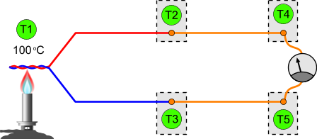
Any junction between two dissimilar metals, will perform a thermocouple! That is where the whole problem begins. Suppose that we have a K-type thermocouple. We will need to connect both wires of the pair to copper wires, either because we want to extend the wires, or because we want to connect the multimeter. These connections will create another thermocouple pair. The following drawing demonstrate this circuit:
The red and blue wires comes from the K-type thermocouple. The orange wires are copper wires. Thus, due to the first law, T4 and T5 will not create any difference as the wires are always copper. So, we can re-write the circuit as follows:
The problem is that, at the points where the thermocouple wires are connected with the copper wires, two new thermocouples are created! Thus, these thermocouples will create EMF (Electro Motive Forces) to the circuit and alter the readings.
@Joseph the output is DC so you cannot step-it up with a transformer. You can amplify it with an OP-AMP though.
You can indeed use pipes to increase the temperature, but... why?
Is it possible to use some form of transformer to step-up the voltage?
One other idea: Is it possible to use black painted pipes to create a lot of heat using solar as the power?
If a thermocouple with 2 junctions with temperatures T1 and T2 produces a voltage difference V1, and voltage difference of V2 in temperatures T2 and T3, then voltage generated when the temperatures are T1 and T3 will be V1 V2.
@Nhuan I suppose (but have not test) it will be as if you have 2 TCs connected in parallel. The lower temperature will appear. The higher temperature with higher voltage will be consumed as heat dissipation in the closed branch of the two shorted points (as if you have 2 voltage sources of different voltage connected in parallel).
At 12 September 2013, 20:49:35 user Nhuan wrote: [reply @ Nhuan]
Hope you can understand my "illustration" below...
What is the effect, if any, if the thermocouple is shorted at any point (e.g."B") before the tip ("A")?
/-------|----------
A B [measurement?]
-------|----------
At 5 August 2013, 1:50:32 user none wrote: [reply @ none]
Ok I am trying to build this exact circuit I know you used Nickel Chromium and Nickel Aluminum wires but what is the thermocouple copper junction made of or what do I do to create one?
At 5 September 2012, 17:44:39 user Ronnie wrote: [reply @ Ronnie]
the very last line of explaining the third law, "... and this corresponds to 20 degrees Celsius", should actually be "... and this corresponds to 100 degrees Celsius".
@Alan the and - goes to an amplifier, you may choose how to connect them (inverting/non-invertig). The PTC increases its resistance with temperature. To if you connect it in series with a supply, the current will drop.
At 9 July 2012, 12:52:46 user Alan wrote: [reply @ Alan]
Giorgos
Wow, that was relatively easy to follow for a layman. The thermocouple is polarized! Yes, so when coupling a thermocouple in a soldering iron to its control amp in its controller. The of the thermocouple goes to of the op-amp? and the - of thermocouple goes to the op-amp -. Is this correct? A PTC will increase the output (millivolts) as the temperature rises?
ANY ONE CAN YOU PLEASE SHERE ME AS DESCRIPTION ABOUT ASEMBLING PROCESS OF A PID TEMPRATURE INDICATER AND CONTROLER................
EMAIL YVKELURU@GMAIL.COM
CONTACT 0-8008325089
At 27 February 2012, 10:26:32 user Nikos wrote: [reply @ Nikos]
Very interesting web site!
Actually I was trying to understand how is possible to depict the thermocouple mV indication on the measuring point using a commercial thermocouple meter/calibrator.Normally these devices depict mV difference between measuring point V1 and junction point V2. The only way to measure (not calculate!) the V1 voltage is by using electronic ice point devices which output the V1 voltage canceling out the error introduced by the cooper wires.
@Johnny no it is not possible. one thermocouple can provide feedback to one controller. it is up to the controller to have more fuctions. a controller may have for example 2 outputs or more.
Excellent! Could someone please let me know if it's possible to connect a single thermocouple but with two outputs? e.g. e thermocouple is connected to the heater and the other end connected to 2 temp displays/meter. Thanks very much.
@vino that is exactly what you need to see, no reading. If you compensate the room temperature and add it to your reading, then you get the real temperature, which in your case is the room temperature. When you heat the junction, you get the added temperature to the room temperature.
If for example room is 20 degrees and you heat the junction to 100 degrees, you must read 80 (100-20)
At 22 April 2011, 16:41:48 user vino wrote: [reply @ vino]
without heating the hot junction of thermocouple,at room temperature can see any reading ,can\'t means why
@ashwin well, no you cannot light an LED efficiently. You can use a peltier thermoelement though. Read here: http://pcbheaven.com/wikipages/The_Peltier_Thermo-Element
Thanks for the article. I never had a idea of what a thermocouple is?
But now I clear about its laws and how it works.
I had one question:
I want to but one thermocouple for my experiment which type I should go for? I will be using a temperature bet -15 to 50 Celsius.
Please lemme know which company provide a accurate Thermocouple?
Good question Harry! According to the 2nd law, if any intimidate material are in the same temperature across all its length, then the reading is NOT affected. Which means that you can add as many materials as you like without affecting the reading, but these materials must be in the same temperatures through all its length.
At 4 February 2011, 18:32:55 user Harry wrote: [reply @ Harry]
A very nice and clearly explained article.
One question though: The wires leaving from the reference junction are both copper all the way to the terminals of the voltmeter so no additional EMF is generated as they are homogeneous materials. That's all good...
But especially in digital multimeters or data acquisition boards, the voltmeter terminals themselves might be made out of something else than copper, so can you really eliminate T4 and T5 from your diagram? Wouldn't you actually have two more junctions there? Or do you say that the terminal internal wire length is so small that it is isothermal, and thus you can treat it according to the law of intermediate metals and say it generates no emf.
The info is the same regardless the metals, as long as they are different. I tried it once with copper wire and iron and worked. As for the formula, it applies as well, yet the "a" values are different. For this reason, when you get e thermocouple, you ask it by its type, for example "K-Type thermocouple". And then google for the "a" values and the corresponding voltage to temperature tables.
At 12 October 2010, 17:30:20 user kjh wrote: [reply @ kjh]
thank you for your nice help does these information or equation at least work for Aluminum &Chromium thermocouple.?
At 12 October 2010, 17:23:39 user kjh wrote: [reply @ kjh]
Oh iam sorry i got the voltage but why you take it to the 8 why you stopped over there !is it for accuracy purposes!
At 12 October 2010, 17:20:54 user kjh wrote: [reply @ kjh]
very nice !
but how did you plug in the voltage .0037 inside that equation (i mean which v is 0.0037v???!!
Fantastic videos!! They really helps in understanding the principle of operation of thermocouples. Now, I will perform the experiments by myself:)Thank you!!!

 Home
Home
 Projects
 Experiments
 Circuits
 Theory
 BLOG
BLOG
 PIC Tutorials
 Time for Science


 Contact
 Forum
Forum
 RSS
RSS


 Reddit this

