PAGE 1 of 2 - How to check the Windings of a 3-Phase AC motor
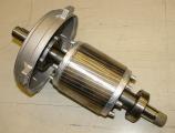
The rotor of a squirrel-cage motor
A typical 3-phase squirrel-cage motor has six connection leads in the electrical connection box for the three coils. If someone works with AC 3-phase motors, then it is important to know how to connect these motors in Star and Delta connection, and how to detect an electrical problem. There are basically 4 problems that the motor windings can suffer from:
Broken coil (infinite coil resistance)
Short-circuited coil (less than normal or zero coil resistance)
Leaking coil to ground (current leaking from one coil to ground/neutral)
Two or more coils short-circuited with each other (current leaking from one coil to another coil)
All of the above problems can be detected with a simple Ohm-meter. First of all, you need to understand how the coils are connected with the six motor leads that exist in the electrical connection box. Here is a photo from a typical electrical connection box:
As you can see, there are indeed six leads arranged in two rows. Since each coil has 2 endings, it is easy to understand that these six leads can be separated in three pairs, and each pair is connected to one coil. It sounds logical to separate these 3 pairs in a vertical pattern, but that's not the way it goes. Instead, the pairs are in cross-pattern like this:
You may now wonder, why the coils are connected in cross-pattern and not vertically... The answer is simple: To easily bridge a permanent connection. A permanent connection is when the motor is connected in either Star or Delta, and this connection is not supposed to changed during the operation of the motor. This is usually done if the motor is small (smaller than 3.5 KWatts) or if the motor is driven by an inverter or some kind of electronic driver. A permanent connection is accomplished with 2 or 3 metallic bridges.
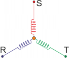
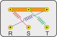
Suppose for example that the motor is connected in Star. In a star connection, each one of the 3 phases (R-S-T) is connected at one end of each coil. The other ends of the coils are connected together in a common point. A star connection can be easily accomplished simply by bridging one of the two horizontal rows in the connection box of the motor. The phases are then connected on the leads of the other horizontal row:
 |
 |
 |
| This is why we call this type of connection "Star" (or Y) |
A star connection is accomplished simply by bridging one horizontal row in the connection box |
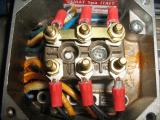
This is a photo from the connection box of a motor connected in Star |
Suppose now that the motor is connected in Delta. In Delta connection, the end of each coil is connected with the start of another coil. The 3 coils are then connected in a circle, creating thus 3 nodes. The 3 phases are then applied on these nodes. A Delta connection is easily accomplished by bridging the 3 columns in the connection box vertically:
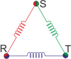 |
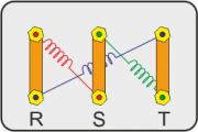 |
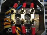 |
| This is why we call this type of connection "Delta" (from the Greek letter Δέλτα) |
A Delta connection is easily accomplished by bridging the 3 columns in the connection box vertically |
This is a photo from the connection box of a motor connected in Delta |
There is one last thing to know: All 3 coils must have the same resistance. That is of-course easy to understand why, so there is no need to explain any further.
Checking the coils of an unconnected motor
Being a motor unconnected, means that there are no Star or Delta bridges on its leads. This is the most straight-forward case to understand. All you have to do is try to find the coil pairs in the electrical connection box. Let's give numbers to the 6 leads:
Suppose that you start from lead 1 and you want to find it's pair. You connect the first probe of the ohm-meter to lead 1, and then you connect the other probe of the ohm-meter to leads A, B, C, 2, 3 and ground (motor chassis).If the motor has no problem, then you must find infinite resistance between all leads and ground, except from one lead. This one cannot be lead A though, because -as we said- coils are connected in cross pattern.
Then, you repeat the same process but this time you connect the first lead of the ohm-meter to lead 2, and the second lead to leads A, B, C, 3 and ground. Notice that you do not need again between 2 and 1 since you've measured already before. Again, you must find infinite resistance between all leads and ground, except from one lead. This lead cannot be the one opposite to 2 (which is the lead B) and of course cannot be the lead that pairs with lead 1 (found from the previous measurement).
Finally, you repeat the same process with the first probe on lead 3, and the second probe on leads A, B, C and ground. Now, you know exactly which of these 3 leads pairs with lead 3. If for example you found that lead B pairs with 1 and lead C pairs with 2, then obviously lead A pairs with 3.
Additionally, you can compare the resistances between the pairs. If they are all equal, then you have a very well manufactured motor. A tolerance of 5% (and some times 10%) is generally accepted. If the difference is bigger, this could mean that some wires of the coil are short-circuited and the overall coil length is shorter. This is the most difficult problem to identify in such a motor. Usually, if the motor has short-circuited windings, it won't take long until this specific coil it is totally destroyed.
In short
You must find the same resistance between 3 pairs of leads ONLY
These pairs must be in cross-pattern as explained before
There must be absolutely no connection (infinite resistance) between all other combinations
There must be absolutely no connection (infinite resistance) between the leads and the ground
Comments
At 15 March 2016, 5:53:51 user Ashraf Mortada wrote: [reply @ Ashraf Mortada]What is the allowed tolerance for winding resistance as per standard?
At 9 March 2016, 17:18:43 user Naseem wrote: [reply @ Naseem]I m very thankfull to u bcoz it is very clear concept. Today my all doubts are clear abt motor connection.
At 6 March 2016, 12:38:34 user moses mathe wrote: [reply @ moses mathe]
At 21 February 2016, 23:59:37 user narendra wrote: [reply @ narendra]Excellent article and photos
At 11 February 2016, 2:55:18 user rizuan wrote: [reply @ rizuan]
At 28 January 2016, 19:27:07 user innocent olo kubacha wrote: [reply @ innocent olo kubacha]
At 18 January 2016, 14:26:59 user Avtar Singh wrote: [reply @ Avtar Singh]Excellent work. Very helpful.
At 30 December 2015, 5:16:05 user Shahin wrote: [reply @ Shahin]
At 29 December 2015, 19:15:38 user santhosh kumar wrote: [reply @ santhosh kumar]
At 28 November 2015, 2:41:10 user Thein wrote: [reply @ Thein]
At 24 November 2015, 13:07:22 user Vins James wrote: [reply @ Vins James]It was written so well, in clear and simple language , without leading to any confusion. Really good.
At 3 November 2015, 13:00:53 user rajatoseer wrote: [reply @ rajatoseer]its really such a good thing which i did not know before. Thanks
At 2 November 2015, 6:25:09 user M.Ebin Nisanth wrote: [reply @ M.Ebin Nisanth]
At 29 September 2015, 11:59:08 user parthiban wrote: [reply @ parthiban]5 HP MOTOR resistance value how much
At 19 September 2015, 13:53:32 user Shakeel ahmed wrote: [reply @ Shakeel ahmed]
At 19 August 2015, 12:44:29 user Joan Myers wrote: [reply @ Joan Myers]Hi. We have a Myers Submersible water pump model 3ST52-5-P4 that doesn't work. My husband cut the wires and took some resistance readings . It has 4 wires . There was no reading between any of the wires and the green one which he assumes is the ground. The reading between the black and red = 22 ohms , red and yellow = 20 ohms , black and yellow = 4.7 ohms. Do these reading point to a problem with the motor.
Thank you
At 16 August 2015, 18:11:32 user Interesting wrote: [reply @ Interesting]I love this explanation and it gives boldness to my career
At 13 June 2015, 2:10:49 user Kiran Kumar wrote: [reply @ Kiran Kumar]Very good explaination, anybody can understand easily immediately:-
At 21 May 2015, 9:16:44 user k.prakashkesavan wrote: [reply @ k.prakashkesavan]what is the DG power to solor power in generator ple..
At 20 May 2015, 14:09:45 user SAMUEL VARGAS wrote: [reply @ SAMUEL VARGAS]
At 9 May 2015, 21:23:32 user Anthony wrote: [reply @ Anthony]Excellent article and photos
At 14 April 2015, 11:05:46 user yogender sharma wrote: [reply @ yogender sharma]easy way to known the connection of induction motor .
At 10 April 2015, 1:33:03 user Subhranil Mallick wrote: [reply @ Subhranil Mallick]Thank you, its very easy to get the basic knowledge.
At 16 March 2015, 15:31:09 user Isuru Jayaranga wrote: [reply @ Isuru Jayaranga]
At 10 March 2015, 13:53:35 user husnain wrote: [reply @ husnain]1 phase:220 v
2 phase:440 v
why 3 phase is not equale to 660 v.its resion?
At 8 February 2015, 18:24:00 user johnny magtulus wrote: [reply @ johnny magtulus]Thanks alot very helpful tips in my work.God bless more tips
At 8 February 2015, 17:29:28 user vishwanath badiger wrote: [reply @ vishwanath badiger]
At 17 January 2015, 13:57:19 user Ganesh wrote: [reply @ Ganesh]If you give how to identify starting end and finishing end in a coil it is more useful. Just try to give that information
At 8 January 2015, 22:14:26 user danny wrote: [reply @ danny]
At 4 January 2015, 16:31:14 user jackking wrote: [reply @ jackking]
At 28 November 2014, 19:48:12 user Guest wrote: [reply @ Guest]Brief and thorough. Just a great piece of technical writing!
At 18 November 2014, 14:35:54 user Michael L. Rappaport wrote: [reply @ Michael L. Rappaport]Beautifully written and illustrated article. It would be good if material could be added about the result of not having one phase in both the Y and delta configurations.
Aside: it's = it is.
At 11 November 2014, 15:45:58 user SAHIL wrote: [reply @ SAHIL]
At 10 November 2014, 17:07:16 user SUNIL GHORPADE wrote: [reply @ SUNIL GHORPADE]You cleared all my doubts. Thanks
At 10 November 2014, 16:27:30 user kishore wrote: [reply @ kishore]This is really soo good.. this is usefull
At 23 October 2014, 1:09:22 user Michael A. White wrote: [reply @ Michael A. White]Do you have same information for 12 lead 3 phase motor? thank you
At 20 October 2014, 18:05:29 user sahil wrote: [reply @ sahil]
At 12 October 2014, 1:54:44 user Anil kumar wrote: [reply @ Anil kumar]This article is very good
At 4 October 2014, 13:49:11 user dinesh kumar thakur wrote: [reply @ dinesh kumar thakur]
At 17 September 2014, 1:07:57 user bulelani wrote: [reply @ bulelani]I was doing my trade test, motor test task. I found out my windis are not da same while doing continuity test with my meter. Now I had to balance the windings, I had 21.3 on U and 10 on V but infinity (OL) on W windimg. I could not calculate my percentage difference becouse onfinity is too big it has mo value. My qiestion what was I surpose to do?? I knw da formula to calculate percentage difference its=
Percentage diffence = Resistance high-Resistance low all/ divoded by resistance high tymes 100%. Whts infinity value?? Or my amswer
At 13 September 2014, 15:46:07 user Manfred Frost wrote: [reply @ Manfred Frost]Thanks. Concise and easy to understand, although not what I was looking for.
At 10 September 2014, 5:04:58 user Kevin Brierley wrote: [reply @ Kevin Brierley]A very clear laid out explanation, been a electrician mate i have no understanding of motors, we had a fault the other day on a motor, & i wondered how they would test it, Well now i do, now i even no about STAR DELTA.
Nice one
At 9 September 2014, 6:42:07 user SS SHAH wrote: [reply @ SS SHAH]How do we know standard resistance/inductance value of 3-phase induction value for different capacity and speed of individual motor ?
At 8 September 2014, 19:20:55 user monu wrote: [reply @ monu]How do we know the terminal a1a2 b1b2 c1c2 if there are not marked A B C 1 2 3 ? I hope you understand my question that there is no identification of A1A2 B1B2 C1C2 SO HOW DO WE UNDERSTAND THAT A1A2 B1B2 C1C2
At 29 August 2014, 16:29:43 user Wellawattage Prabath Madushan Peris wrote: [reply @ Wellawattage Prabath Madushan Peris]you have explained this very well.you have done a big task.thank u.
At 11 August 2014, 7:14:05 user hashim m rusambi wrote: [reply @ hashim m rusambi]how can instol the winding motor
At 28 July 2014, 6:42:37 user DEEPAK wrote: [reply @ DEEPAK]How do we know the terminal a1a2 b1b2 c1c2 if there are not marked A B C 1 2 3 ? I hope you understand my question that there is no identification of A1A2 B1B2 C1C2 SO HOW DO WE UNDERSTAND THAT A1A2 B1B2 C1C2
At 13 July 2014, 18:11:37 user ramprakash wrote: [reply @ ramprakash]I want a motor winding checking list by ohm and any checking method because I was a face a last time problem I am checked the motor proper by continuity all ok so start the motor and its blast and I am face manny problem because I done the maximum work 5kw to 200 kw.
At 12 July 2014, 15:20:33 user subrata mukherjee wrote: [reply @ subrata mukherjee]in a single phase oil circulating motor,i test in my section continuously 4 hours.there were no probelem.rating of the motor is 7.5Amp,230V,but when it connect in motorcoach (inCOMPLETE OIL CIRCUIT) sometimes it appears taking high current,motor was not running,abnormal sound etc.what is the reason? please tell me.
At 1 July 2014, 23:48:04 user coltmanneil wrote: [reply @ coltmanneil]I have a twin speed 3 phase motor high/low speed ,at some point terminal block has been taken away.How can i find the high and low speed windings.??Thanks
At 22 June 2014, 5:52:13 user ADAMSON wrote: [reply @ ADAMSON]A 3 phase motor for a washer with the following details:
type A12H4d-23
Y = 190v 3phase 50hz speed:1455 RPM Curent:7.5A P2:1.5Kw
IP:20 I.C:F part number 438970561
The machine is indicating Error motor too hot after running for 4minutes.The winding resistance is 1.4ohms across the phases in star(uniform values).When running,one the current results obtained are::
L1=2.5Amps L2=1.6amps L3=2.5Amps while phase to phase voltage=62.15volts and phase to neutral= 135volts(in low speed).The motor is supplied from a motor control unit which takes in single phase(220v) and delivers three phase to the motor.
Please help.
At 7 June 2014, 0:56:48 user jithendra wrote: [reply @ jithendra]
At 31 May 2014, 13:01:04 user chris wrote: [reply @ chris]Ohmmeter can not detect a partially shorted windings specially when you're dealing with a larger motors. The best equipment to use is the microhmeter. And also you can use LCR to measure the inductances of each winding. May I request you to give a procedure in measuring the inductances using the LCR.
Thank you
At 18 May 2014, 19:36:26 user Deepak kumar purohit wrote: [reply @ Deepak kumar purohit]Very easily you explained it, very nice
At 29 April 2014, 2:02:52 user Hereimjay_81@yahoo.co.in wrote: [reply @ Hereimjay_81@yahoo.co.in]
At 3 April 2014, 13:12:54 user vijay sagar pyda wrote: [reply @ vijay sagar pyda]
At 31 March 2014, 16:02:12 user Bill Bastenbeck wrote: [reply @ Bill Bastenbeck]Great info- very informative. Thanks!
At 23 January 2014, 21:14:27 user Mike wrote: [reply @ Mike]
At 7 January 2014, 18:14:52 user Sankarappan wrote: [reply @ Sankarappan]Relly, very useful to my knowlage.
At 31 December 2013, 21:08:43 user Skip wrote: [reply @ Skip]Sir,
Simply put your explanation of star and delta connections is probably the best one I have come across!
Keep up the good work, you have a rare quality you must use to its max !
At 30 December 2013, 8:37:09 user Giorgos Lazaridis wrote: [reply @ Giorgos Lazaridis]@Asokarasan Once i had a motor from a coil repair and the guy had this mistake as you mention it. It stalls and makes noise.
At 26 December 2013, 16:23:37 user Asokarasan wrote: [reply @ Asokarasan]if A-A1,B-B1,C-C1 is coil sequence in delta connection ,if we change A1-A, B-B1,C-C1 what will happen motor
At 4 December 2013, 8:01:57 user krishnamoorthy wrote: [reply @ krishnamoorthy]really interested in your lecture on resistance measurement. is highly knowledge to me.
At 31 October 2013, 10:03:41 user Mohamed Rafi wrote: [reply @ Mohamed Rafi]I really loved your lecture on resistance measurement. is highly facilitating.
At 25 October 2013, 2:00:11 user selladurai wrote: [reply @ selladurai]i'm like this circuit connection . Any more impede send mail
At 14 October 2013, 6:05:52 user LAKSHMI NARAYANA REDDY Y wrote: [reply @ LAKSHMI NARAYANA REDDY Y]Dear Sir,
I would like to know the connection (star star/star) two speed three phase squirel cage motor also the connection (star/-star) that i saw those connection in ASIA type motors and supporting your answering by drawings(line voltage is 380vac)thankyou
At 14 September 2013, 2:40:05 user ch zeeshan wrote: [reply @ ch zeeshan]
At 13 September 2013, 21:38:50 user Giorgos Lazaridis wrote: [reply @ Giorgos Lazaridis]@Daramola Dele It depends on the power and type of the motor. It may have less than 1 ohm resistance or much higher.
At 13 September 2013, 18:38:49 user Daramola Dele wrote: [reply @ Daramola Dele]I really loved your lecture on resistance measurement. is highly facilitating.
however, what is the minimum acceptable resistance and insulation resistance for a motor?
At 24 July 2013, 7:15:50 user Giorgos Lazaridis wrote: [reply @ Giorgos Lazaridis]@Shawn Hall Always talking about Y connection, between common and any terminal is the lowest resistance, between two terminals is the highest.
At 17 July 2013, 5:22:42 user Joseph Wilfred Unekwu wrote: [reply @ Joseph Wilfred Unekwu]Thanks alot you just open my a new chapter to my knowledge.
At 12 July 2013, 15:02:01 user Shawn Hall wrote: [reply @ Shawn Hall]When testing the windings od a single phase motor,
Technician #1 says that the common and the run terminals show the lowest resistance.
Technition #2 says that the pair of terminals with the highest resistance will indicate that the other terminal is the common.
Who is correct?
A. Technician #1 only.
B. Technitian #2 only.
C. Both technicions #1 and #2.
D. Neither technicions #1 or #2.
I think the answer is D?
At 15 June 2013, 6:32:38 user Giorgos Lazaridis wrote: [reply @ Giorgos Lazaridis]@Robert Chadwick 3-phase AC induction motor Star connection? Then it is dead.
At 13 June 2013, 22:56:29 user Robert Chadwick wrote: [reply @ Robert Chadwick]I have a 3 phase motor, and I am able to the 3 leads that go into the motor I get no resistance between 2 of the leads, and 33 OHMS from either one of those to the third lead. what does that mean
At 3 June 2013, 17:43:16 user Eswaran wrote: [reply @ Eswaran]@samantha @samantha. if we change the connection RPM will not change. this 2 connections related for voltage & current only. if the connection is star current will low sameas voltage should be costant 415v. delta current will high but motor will start at littlebit low voltage also. RPM related only NO OF POLES and Effeciency of motor
At 3 June 2013, 13:50:17 user danilo de vera wrote: [reply @ danilo de vera]I had a 3 phase ac motor i want to to connect to power supply and the control was starting by star then delta (6 leads) my problem is the si lead came from motor has no marking for the 1,2,3,4,5,6 i cant determine the 1,2,3 and the 4,5,6.please help me
At 11 May 2013, 12:03:24 user Tim Rigsby wrote: [reply @ Tim Rigsby]Will a fifty hz 415 .37kw work on 480 60hz.....?????,I
At 2 May 2013, 5:06:31 user Giorgos Lazaridis wrote: [reply @ Giorgos Lazaridis]@kazi sahriar U1-V1-W1 goes to RST. U2-V2-W2 shorted all together for star connection.
At 29 April 2013, 7:41:01 user kazi sahriar wrote: [reply @ kazi sahriar]dear sir,
my problem is, I have a 3 phase motor which r 6 probe those r U1 V1 W1 & U2 V2 W3.so,how i can connect those terminal.Plzz tell me sir.
At 23 April 2013, 6:22:16 user Shelvindra Bali wrote: [reply @ Shelvindra Bali]I want know if there is any type of book or software showing me all the connection daigrams of the motor. For example like 2star 2delta 3star 3delta 4star 4delta for different rpm and poles
At 16 April 2013, 16:38:23 user Idriss wrote: [reply @ Idriss]That is a very clear explanation. I have read so many topics on this, but this is the first time I actually get it.
At 3 April 2013, 8:57:29 user RADHAKRISHNAN wrote: [reply @ RADHAKRISHNAN]sir,
IN the Motor Winding end wire in 3 phase A1A2, B1B2, C1C2 connected thro RYB the motor will run But if any changes in the terminal connection
A2A1 / B2B1 / C2C1 if the motor winding will get Abnormal heat.
Further, pleas give the diagram for the How to identify the A1, A2 B1, B2,C1,C2 by using TEST LAMP METHOD
At 22 March 2013, 6:53:42 user Geofry wrote: [reply @ Geofry]Thanks for the info above. Its help me a lot.
At 16 March 2013, 12:15:37 user tanveer shah wrote: [reply @ tanveer shah]sir many regards
kindly send me any post notification as to be more informative and conscious about my related field.
thanx a lot
At 15 March 2013, 15:01:50 user Giorgos Lazaridis wrote: [reply @ Giorgos Lazaridis]@Vasilis Caravitis This is the worst case scenario... Star-Delta switches though have schematics how to connect them. You have to consult this schematic. There are 6 connectors, RST and UVW. You connect the first row of motor connectors to R-S-T and the second row to U-V-W
At 11 March 2013, 4:34:37 user Vasilis Caravitis wrote: [reply @ Vasilis Caravitis]Hi, My problem is that I need to replace the Star-Delta change-over switch. The existing 5-position (broken) switch allows also reverse rotation, but I only need one direction of rotation. The rplacement is intended for single direction operation and has a different terminal pattern. How can I determine which cable goes where?
At 5 March 2013, 20:13:07 user Giorgos Lazaridis wrote: [reply @ Giorgos Lazaridis]@Decker auto electric This motor must be connected in star probably (i may be mistaken though). Connect the 3 poles on one side all together, and then apply RST to the other 3 opposite poles
At 4 March 2013, 22:04:59 user Decker auto electric wrote: [reply @ Decker auto electric]I got this electric motor that i can not
Figure out how to connect the internal
Wires coming out of the motor..
Could anybody help me on it???
24 slot. 2 pole lapwinding 2 coils per group
6 groups. 295 rounds per coil. Pitch 1 to 11
440/220 volts 3 ph 3200 rpm
There are only 6 leads coming out of motor
But just can't get the motor running
Thank a lot
At 16 February 2013, 16:33:43 user kevin wrote: [reply @ kevin]Hi does anyone have any ideas about wiring a six wire motor to use on a rotary phase converter because ive tried a few different ways but im getting nowhere, any help is appreciated.
At 6 January 2013, 21:00:17 user Giorgos Lazaridis wrote: [reply @ Giorgos Lazaridis]@samantha none, both will give you the same rpm. Delta will give you (if motor permits) more torque.
At 6 January 2013, 19:10:14 user samantha wrote: [reply @ samantha]pls tel me which connection is giving more RPM? (star or delta)
At 2 January 2013, 8:35:49 user Giorgos Lazaridis wrote: [reply @ Giorgos Lazaridis]@Abbas musa there is no formula. It depends on the wire thickness and length.
At 2 January 2013, 2:28:13 user geoff wrote: [reply @ geoff]Well presented explanation. This is a good site for electrical mechanics.
At 1 January 2013, 15:42:05 user Abbas musa wrote: [reply @ Abbas musa]helo... Am 4rm Nigeria.please, what is the formula used for calculating the winding resistance of a.c asynchronous motor using the volt-ampere method?
At 20 December 2012, 2:16:37 user John Romano wrote: [reply @ John Romano]Six wires are not a problem. I have a motor that I looked at today that had 9 wires, and two ways to set up. The first is high voltage and the other is low voltage. What is the correct way to check the motor for proper connection?
At 13 December 2012, 15:46:52 user KHALID wrote: [reply @ KHALID]GOOD EXPLANATION, I LEARN TOO MUCH FROM THIS TOPIC.
At 12 December 2012, 20:36:44 user Thamir Kareem wrote: [reply @ Thamir Kareem]Dear Sir,
I would like to know the connection (star star/star) two speed three phase squirel cage motor also the connection (star/-star) that i saw those connection in ASIA type motors and supporting your answering by drawings(line voltage is 380vac)thankyou
At 23 November 2012, 11:43:56 user Aamir mehmood wrote: [reply @ Aamir mehmood]I like very much improve knoldge my self
thanks
At 12 November 2012, 16:54:39 user mahroof.o wrote: [reply @ mahroof.o]it'S EASY TO UNDERSTAND............
At 3 November 2012, 19:04:58 user jonas hamata wrote: [reply @ jonas hamata]
At 31 October 2012, 7:27:30 user Giorgos Lazaridis wrote: [reply @ Giorgos Lazaridis]@atish kumar read 'Checking the coils of an unconnected motor"
At 28 October 2012, 11:29:59 user atish kumar wrote: [reply @ atish kumar]I have the same doubt that..
How would you go about testing the start & end of each motor winding prior to powering up the motor, either by the use of a multimeter or a battery and a volt meter. I understand that one could power up the motor and check the current being pulled by each phase, if there is a serios unbalance on a single winding, then turn that winding around, BUT I would like clarity on how to sort out the windings start and end before power up.
At 24 September 2012, 14:30:09 user ganesh wrote: [reply @ ganesh]may be ur ohm meter problem.
At 20 September 2012, 3:03:18 user kaac.perera wrote: [reply @ kaac.perera]
At 24 August 2012, 7:16:52 user Giorgos Lazaridis wrote: [reply @ Giorgos Lazaridis]@marcus usually 3-phase motors with 3 wires are internally Y or delta connected. It must be on the plate.
At 24 August 2012, 5:23:58 user marcus wrote: [reply @ marcus]and if your three phase motor only has three wires not six - what way do you test it then?
At 21 August 2012, 21:29:29 user T.Sethuram kumar wrote: [reply @ T.Sethuram kumar]Today i got different problem what actually happen one motor got tripped continually so i checked the motor amps its high 12A so i checked the name plate there full load current 12A so that i removed the load and checked after that also same current 12A how it's i confused because with load 12A without load also 12 A so that i checked the winding resistance that is ok 3phase equally, after that i checked bearing that also good winding also good then how this it's happen anybody knows kindly reply me
At 18 July 2012, 8:19:57 user Francisco Gavina wrote: [reply @ Francisco Gavina](Portugal) Great tutorial. I am 51 years old, I am self taught. I'm unemployed. I like learning things of quality. I like to diversify knowledge. It will not let me grow old. Thank you. Gavina.
At 21 May 2012, 11:30:55 user Giorgos Lazaridis wrote: [reply @ Giorgos Lazaridis]@Ian Ellis there are 6 connectors on a 3-phase squirrel cage motor. You can test them with multimeter, ohm-meter or battery by following the instruction if the first page of this theory, at the bottom (Checking the coils of an unconnected motor)
At 20 May 2012, 5:29:49 user Ian Ellis wrote: [reply @ Ian Ellis]How would you go about testing the start & end of each motor winding prior to powering up the motor, either by the use of a multimeter or a battery and a volt meter. I understand that one could power up the motor and check the current being pulled by each phase, if there is a serios unbalance on a single winding, then turn that winding around, BUT I would like clarity on how to sort out the windings start and end before power up.
At 6 January 2012, 19:43:50 user Kammenos wrote: [reply @ Kammenos]@George excellent! I am working on a simple coil checker tool (that is why i uploaded this theory after all). I will check this link and see if i can add it as a function. ;) thanks.
At 5 January 2012, 23:42:46 user George wrote: [reply @ George]one other thing.
NEVER WORK ON AC system by yourself, ALWAYS have another person there as the SAFETY person. To switch off the power, and/or save your butt/ life if anything goes seriously wrong
At 5 January 2012, 23:39:19 user George wrote: [reply @ George]@Paul - there are two methods for checking phase of windings mentioned on cr4.globalspec.com/thread/71498
One uses a push button DC voltage and a galvanometer .
The other uses live AC voltage on 1 winding against the other 2 windings connected in series to see if there is a net 0V AC or double the test winding Voltage, BUT beware YOU ARE WORKING WITH LIVE AC POWER. So make sure that you have tested for earth faults. [A multimeter is not really the greatest here a megger would be better] AND DO NOT TOUCH ANYTHING WHEN LIVE - use INSULATED PROBES
At 5 January 2012, 16:17:57 user Kammenos wrote: [reply @ Kammenos]@Paul :D :D i'll tell you a little secret. The motor that is the photos, is a repaired motor that had a burned coil. The (not so good) technician that repaired the coils connected one of them the opposite direction. I tried hard to find a way to measure that problem, but had no luck with simple instruments. You connect it in the supply and if it makes noise and does not rotate, or rotate with no torque, then change connection...
At 5 January 2012, 16:03:36 user Paul wrote: [reply @ Paul]Just wonderin...
Some time ago I also had to figure out how to connect a 1.5KW three phase motor but on this motor there was not such a nice board for connecting the wires. It basically had 6 loose wires dangling from it.
A big problem would be if one of the phases is connected backwards relative to the other 2.
How do you check for that?
In the end I just (sort of) guessed, but I took some extra precautions to prevent destroying a perfectly good motor.
I guessed right but didn't feel happy about it. |
|
 HOT in heaven! HOT in heaven!

|
|

 Home
Home
 Projects
 Experiments
 Circuits
 Theory
 BLOG
BLOG
 PIC Tutorials
 Time for Science
 Contact
 Forum
Forum
 Projects
 Experiments
 Circuits
 Theory
 BLOG
BLOG
 PIC Tutorials
 Time for Science
 RSS
RSS