PAGE 6 of 6 - Injecting PWM pulses to control the brightness of the LEDs
Injecting PWM pulses to the single transistor LED driver
These are the circuits we've discussed in Page 2 and Page 3 of this tutorial. This is how can someone inject PWM pulses:
Remember that the PWM controller i use sinks current and does NOT source. The base of the transistor grounds on every pulse of the generator, thus the transistor turns off completely, turning off the LED as well.
The same applies of course for the other 2 circuits. The pulses are injected directly at the base junction of the transistor.
 |
 |
 |
 |
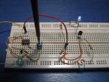
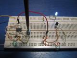
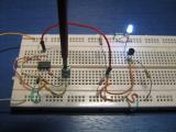
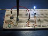
| Dimmed LED with PWM pulses injected into the base of the transistor |
Higher duty cycle means brighter LED |
Higher duty cycle means brighter LED |
Full brightness. PWM pulses are not so linear as the direct current control shown before. |
Injecting PWM pulses to the Transistor - MOSFET driver
For the transistor - MOSFET driver that we talked in Page 4, the best position to inject the PWM pulses is the gate of the MOSFET. The gate resistor RG will act as a pull-up resistor for the PWM generator.
Comments
At 19 October 2015, 14:13:48 user Jakoos wrote: [reply @ Jakoos]There seems to be an inconsistency in your measured values.
The sum of the voltmeter readings should be around 11.3V 0.7 for Rs = 12V for Vdd.
The actual values in the first picture is:
Vdd = 3.36V 8.03V 0.7V = 12.06V Correct.
The value for the second picture is:
Vdd = 3.36V 4.43V 0.7V = 8.49V Which is wrong. It should have been 12V.
Two errors is visible. a) the Vled would be higher in the second instance most probably at 3.5-3.6V while the Vfet should be the difference. You cant loose voltage in a circuit. It must be somewhere and we know it is not on Rs as the transistor will keep it at 0.7V,
At 19 October 2014, 16:40:28 user Giorgos Lazaridis wrote: [reply @ Giorgos Lazaridis]@Charles For 1W led better use a constant current driver, like the single transistor one.
At 18 October 2014, 2:28:07 user Charles wrote: [reply @ Charles]I know most all of your suggestions talk about how the resister is a loss of power. If one was to use a buck converter to step the V down to 3.2, what option would be best to limit current to 1w LED's.
At 14 September 2014, 15:15:54 user Kothandapani wrote: [reply @ Kothandapani]please send some notes of led and led driver then and there
thanks for services
truly yours,
kothandapani
At 3 September 2014, 6:03:09 user duncan wrote: [reply @ duncan]Just wanted to say thanks for sharing. Your presentations are very clear and informative.
At 2 August 2014, 2:56:09 user Ancel wrote: [reply @ Ancel]@Giorgos Lazaridis Hi, I'd like to create a 7 segment constant current driver using these transistors. Is there a way to use a single resistor current reference or will I need one for each segment?
At 6 May 2014, 7:44:48 user Giorgos Lazaridis wrote: [reply @ Giorgos Lazaridis]@oliver You can connect the output of the arduino at an open-collector transistor circuit. Say a 1K resistor goes to the base of an NPN, the emitter goes to the ground and the collector goes to the input of this circuit. It will provide enough sink current.
At 20 April 2014, 16:23:39 user oliver wrote: [reply @ oliver]@Giorgos Lazaridis
Thanks for the great tutorials. With the transistor-MOSFET driver, when connecting an Arduino PWM pin, only half the current is flowing through the LED, even at 100% duty cycle. I assume this PWM is not sinking current? How to connect an arduino (or any microcontroller PWM output) properly?
At 18 April 2014, 10:51:40 user MaxiD wrote: [reply @ MaxiD]I can put another transistor that controls the gnd bjt transistor for use with pwm?
At 22 March 2014, 16:13:13 user Giorgos Lazaridis wrote: [reply @ Giorgos Lazaridis]@Leon Not quite sure, sorry
At 18 March 2014, 19:55:22 user Leon wrote: [reply @ Leon]can we apply this to operate a laser diode?
At 2 February 2014, 9:34:02 user Giorgos Lazaridis wrote: [reply @ Giorgos Lazaridis]@karthikeyan check out the datasheet of the LED, this is where you find the info
At 2 February 2014, 9:28:06 user karthikeyan wrote: [reply @ karthikeyan]dear sir can you send to my email about ampere and voltage of one led
At 27 December 2013, 5:21:45 user thiru wrote: [reply @ thiru]VR voltage 230vAc and LED voltage is 15vAc now resistor value? so please send the formula as soon as possible.
At 14 December 2013, 23:58:32 user fabelizer wrote: [reply @ fabelizer]Very helpful! Thanks for all your work!
At 14 October 2013, 19:14:30 user Giorgos Lazaridis wrote: [reply @ Giorgos Lazaridis]@yony Simply provide PWM pulses to the proper PWM input of the circuits is the easiest way. Foe more sophisticated solutions you have to do the research yourself
At 14 October 2013, 13:44:32 user yony wrote: [reply @ yony]Can you please show how can these circuits be incorporated with a microcontroller?
I'm in a search for an efficient way to drive a 1 watt LED via Arduino (right now I'm using a non-efficient way to do this with a TIP120 transistor and 2 resistors which one of them needs to be at least 1 watt resistor).
Thank you
At 16 June 2013, 8:03:14 user jai ochani wrote: [reply @ jai ochani]please advice me the circuit diagrm for 12v out put, 2Amp led driver.
At 14 February 2013, 17:14:10 user Giorgos Lazaridis wrote: [reply @ Giorgos Lazaridis]
At 11 February 2013, 11:46:22 user shamim wrote: [reply @ shamim]we wanted to drive a LED using Mosfet. what Mosfet to use???
At 16 January 2013, 15:39:39 user Giorgos Lazaridis wrote: [reply @ Giorgos Lazaridis]@Ian for 90% efficiency you will need other type of circuits, not a linear driver. An SMPS instead
At 14 January 2013, 13:22:32 user Ian wrote: [reply @ Ian]Hi Giorgos,
I'm wishing to use currents between 10mA and 1A depending upon the type of LED connected. I'd like the efficiency to be 90% plus if possible. I've seen Rds(on) values as low as 0.021 ohm, which I'd guess would translate into less power losses?
I'm guessing that from a 5v PIC micro that a logic level mosfet is the only way to go as opposed to a normal mosfet?
Thank you, Ian
At 14 January 2013, 9:17:48 user Giorgos Lazaridis wrote: [reply @ Giorgos Lazaridis]@Ian depends on the current and your efficiency requirements. Typically, on resistance of mosfets is very low. In many cases it is lower than 1Ohm (not high current mosfets). What current requirements you have? More than 1 amp?
At 11 January 2013, 17:49:19 user Ian wrote: [reply @ Ian]Hi Giorgos, Thank you for your help with current measurement. Can you also tell me in the selection of a power MOSFET if Rds(on) should be as low as possible or doesn't it matter? I'm presuming the MOSFET is operating in saturation mode or would be if PWM was applied to the gate? Thank you, Ian
At 7 January 2013, 5:34:43 user Giorgos Lazaridis wrote: [reply @ Giorgos Lazaridis]@Ian I put the scale of the multimeter to amperes and connected it in series with the LED
At 6 January 2013, 22:01:19 user Ian wrote: [reply @ Ian]Hello Giorgos, Could you tell me how you measured the current through the LEDs as shown in your photos please? Thank you, Ian
At 3 January 2013, 8:41:11 user adithyan wrote: [reply @ adithyan]Circuits are plenty for pwm control of led brightness. It is agreed that there cannot be a linear control of led brightness. Assuming that the pwm controls applied and the led current exceeds the 20ma limit in case of 4mm and 5mm Leds and 350ma in one watt, how a feed back control either shuts off the led or keeps the led current at maximum is yet to be published
At 2 October 2012, 15:17:29 user Ajay wrote: [reply @ Ajay]Pls. give detail related to LED Driver Design.
Regards
Ajay
At 28 September 2012, 18:38:22 user Giorgos Lazaridis wrote: [reply @ Giorgos Lazaridis]@kwstas there is no "specific" number. I would not go above 3.3 volts though, just to maintain the power dissipation on the emitter resistor low.
At 27 September 2012, 7:44:27 user kwstas wrote: [reply @ kwstas]@Giorgos Lazaridis Thank you very much but i'm asking about the zener diodes..
At 26 September 2012, 17:48:15 user Giorgos Lazaridis wrote: [reply @ Giorgos Lazaridis]@kwstas same diodes (1n4001 if i remember well or similar)
At 26 September 2012, 17:15:07 user kwstas wrote: [reply @ kwstas]I would like to tell me what diodes did you use for the 1w Led.
Thank you
At 9 March 2012, 8:53:16 user Giorgos Lazaridis wrote: [reply @ Giorgos Lazaridis]@Ghlargh although i plan to use such drivers, i will not go into details.
At 9 March 2012, 8:46:17 user Giorgos Lazaridis wrote: [reply @ Giorgos Lazaridis]@Alvie it is the most stable of all. i tried it with 10w led. i prepare video for this.
At 9 March 2012, 7:46:04 user Ghlargh wrote: [reply @ Ghlargh]You should, if possible, explain how multiple constant current drivers with a single reference resistor work. Such as the Allegro A6282
At 8 March 2012, 22:13:28 user Alvie wrote: [reply @ Alvie]Regarding the BJT MosFET circuit:
Can you prove it's stability ? Just by looking at the diagram I think it might oscillate, eventually at high frequencies, and eventually amplify the thermal noise.
At 7 March 2012, 20:10:23 user Daniel wrote: [reply @ Daniel]hey you should take a look at how leds could be used as sensors(ldrs)
http://www.instructables.com/id/Light-Sensing-LEDs/
At 26 February 2012, 6:32:30 user Giorgos Lazaridis wrote: [reply @ Giorgos Lazaridis]@Lupin Thank you very much for pinpointing those mistakes. You are right for both. The first one is already corrected, as for the second i will recompile the video. Thanks for noticing it soon.
At 25 February 2012, 22:54:05 user Lupin wrote: [reply @ Lupin]Just wanted to mention, tha in the example it seems you forgot to subtract V_Z in the calculation of I_RB_MAX.
On the other hand, I got an issue on how you calculated P_RB in the video (around 5:50). You added the base current to I_RB_MAX. Isn't that already included?
Still many thanks for all the explanations and videos! I'm teaching a beginners electronics course (diodes, transistors, opamps) next semester at uni. Teaching applications, when you got to do theory first always falls short. I guess I'll refer some students to your page if they want to know more. |
|
 HOT in heaven! HOT in heaven!

|
|

 Home
Home
 Projects
 Experiments
 Circuits
 Theory
 BLOG
BLOG
 PIC Tutorials
 Time for Science
 Contact
 Forum
Forum
 Projects
 Experiments
 Circuits
 Theory
 BLOG
BLOG
 PIC Tutorials
 Time for Science
 RSS
RSS