|
 Home Home
 Projects Projects
 Experiments Experiments
 Circuits Circuits
 Theory Theory
 BLOG BLOG
 PIC Tutorials PIC Tutorials
 Time for Science Time for Science
|
| ||
|
General knowledge about instructions The PIC family has a very short range of instructions. With just about 35 instructions, there may be times where you need to find complicated solutions for operations that you thought as standard, such as a division or multiplications for example, that there is no direct instruction for them. All instructions have just about the same format. First comes the name of the instructions. Then, comes the instructions fields. The fields may be none, one or two, according to he instruction. They could be filled with wither a register file address (f), a bit address (b), a literal field, constant data or label (k) or a destination selection (d). Register file address (f) A register file address is a field that indicates the absolute position of a register within the RAM. This field could be filled with either a number (e.g. 0x05h for the PORTA register) or a register name, as long as this name has been previously declared. Bit address (b) 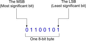 Each byte is composed by bits. For the 8-bit PIC 16F88 that we use, each byte is composed by 8 bits. When a field requires a bit address, this means that a number from 0 to 7 must be placed. Number 0 corresponds to the Less Significant Bit (LSB) and it is the most right placed bit in within the byte. Number 7 on the other hand corresponds to the Most Significant Bit (MSB) and it is the most left placed bit in within the byte. Literal field, constant data or label (k) This field is generally a number. This number may be from a previous-defined constant data, or from a label within the code. Destination selection (d) This field can be either 0 or one. It is used in instructions that will return a byte as a result of an operation. The destination field will define where this byte will be stored. If this field is 0, then the byte will be stored in the working register (W). If the destination is 1, then the byte will be stored back to the register that the specific operation began. If the Microchip header file is included within your code, then you can directly write 'W' for 0 or 'F' for file register. The W is the one and only Working Register that exists in the PIC 16 series. This is a 8-bit width register used for general operations. The W register will be your best friend and therefore you need to get used to it really quick. For example, there is no direct way to add a 8-bit number with ti a file register. Instead, you need first to load this number to the W register (using the movlw instruction) and then add the W register to the file register (using the addwf instruction). Comments
No part of this publication may be reproduced, stored in a retrieval system or transmitted in any form or by any means, electronic, mechanical, photocopying, recording, scanning or otherwise without the prior written permission of the author. Read the Disclaimer
All trademarks used are properties of their respective owners.
Copyright © 2007-2009 Lazaridis Giorgos. All rights reserved. |
  
|
 Contact Contact
 Forum
Projects
Experiments
Circuits
Theory
BLOG
PIC Tutorials
Time for Science Forum
Projects
Experiments
Circuits
Theory
BLOG
PIC Tutorials
Time for Science
 RSS RSS
Site design: Giorgos Lazaridis © Copyright 2008 Please read the Terms of services and the Privacy policy |