
|
 Home Home
 Projects Projects
 Experiments Experiments
 Circuits Circuits
 Theory Theory
 BLOG BLOG
 PIC Tutorials PIC Tutorials
 Time for Science Time for Science
|
| ||
|
Compile a program and transfer to the PIC If you have succesfully finished the previous pages, then right now you must have in front of you the MPLAB IDE with the Tutor-1 project loaded, and an assembly source file with some lines that absolutely nothing. If so, then you are ready to go on with the next step: The compile and upload! The compilation 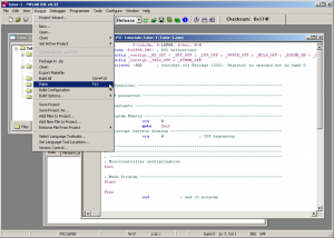 That's the whole idea after all. You need to upload the program to the PIC to make it work. But first, you need to compile it. The compilation is the procedure where the compiler will read the source file and all the included header files, it will check for errors and if all are found normal, it will make a long hexadecimal file. This file will consists of hexadecimal values only. For a human those values does not really mean nothing, but for the PIC this is the language to talk to. When you upload a program to the PIC, all labels and names are lost. Instead, funny hexadecimal values will be used. If you happen sometime to download a program from a PIC to the computer, the only thing you will get are those values. Therefore, you should keep safe backups of your projects and do not rely to the PIC code, because it can only be copied. A maniac could also read and disassembly this bit-yard, but it should be really big deal to worth doing it. The compilation is simply done if you go to the menu Project -> Make. You can click the F10 button as well. When you do so, the results of the compilation shall be shown in the output window. Before you make the next step of uploading something to the PIC, make sure that the output window does not hide any surprises. First of all, there must be the word "BUILD SUCCEEDED" with bold black letters at the bottom of the window. But this is not all. To be sure that the compilation is done successfully, you should watch also for warnings. 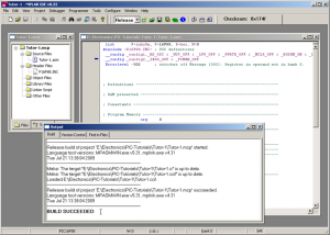 The compiler has errors and warnings. The errors will stop the compilation procedure and a red error message will appear to the output window. You just cannot miss it. Those errors are mainly syntactical errors that makes the execution of the code impossible. The warnings on the other hand warns you about strange situations where care should be taken. The code is able to be executed no matter how many warnings exists. Just make sure that those warnings are caused in purpose. For example, on an 8-bit micro (like the PIC16F88), if you give a value longer than 8 bits, you will get an error that only the 8 lowest bits shall be used. The compilation shall not be halted. But this usually happens due to mistyping of the value. There is no obvious reason why someone would provide a 9-bit value in an 8-bit register. The execution of the program may cause funny results. Just make sure that there is no warning message in the output window. You need to take a closer look as warnings have no distinctive colors or fonts and can easily be missed! Connecting the programmer to the computer for the first time If you have just bought a brand new MPLAB IDE compatible programmer, then you need to do some preparations before you go on. First of all, you need to set the drivers. For this, the MPLAB IDE MUST be already installed. it carries all the drivers for the programmers and it will make your installation easier. 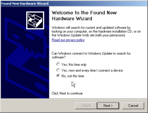 Connect the USB cable to the PC. The 'New hardware wizard' will come up. On the answer select 'not this time' and click 'Next' 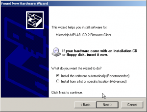 Select 'Install the software automatically' and click 'Next' 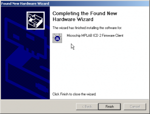 The device is ready to be used. Now you need to inform the MPLAB about your new hardware: 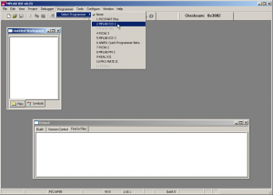 Open MPLAB IDE and with the device connected, go to menu Programmer -> Select Programmer and select your product. 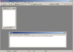 You should get a message that says that the Auto connect is not enabled and the device is not conencted. This is normal. 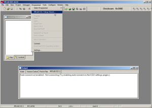 Go to the menu Programmer and select your product's wizard. 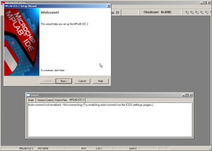 The wizard appears. Click 'Next' to begin 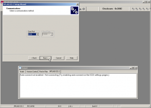 Select the connection port. I use the USB port. If you use a com port, select the baud rate as well. Click 'Next' to continue. 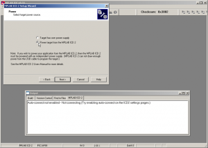 Slect the option 'Power target from the MPLAB xxxx' and click 'Next'. 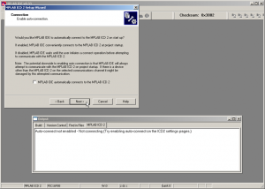 Make sure the 'MPLAB automatically connection' checkbox is unchecked and click 'Next' 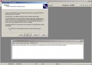 Check the option 'MPLAB automatically downloads the required operating system' and click 'Next'  Click 'Finish' to end. The device is now set. 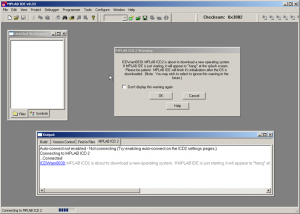 Finally, you will need to download an operating system to the device for the PIC16F88. Every time you program a different chip, you need to download a different operating system. If during the previous procedure you had the according option set, then this will be done automatically when you connect to the programmer and you have select a new device. If a different device is detected, you will get a message box like the one on the left. Just click 'Ok' and wait the procedure to end. My USB ICD 2.5 programmer takes up to 8 second to finish this procedure. It may take significantly more if you have a parallel programmer so you need to be patient. Upload the program to the PIC If the compilation procedure ends with no error (and preferable with no warning), then you are almost ready to upload the compiled hexadecimal file to the PIC. If you have the same programmer with me (ICD 2.5) or another similar and compatible with the MPLAB IDE, then you should follow the next steps. Otherwise, you should advice the manual provided with your programmer for more details. Selecting a programmer and connecting MPLAB with it 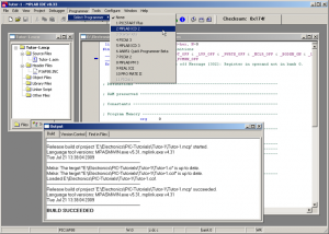 You need to select the programmer at first. You go to the menu Programmer -> Select Programmer and you select the programmer type you own. In my case, i select the MPLAB ICD 2. 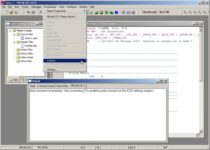 If you do so, it is most possible that a message will appear to the output window saying that Auto connect is not enabled. That is normal because we have not enable the auto connect feature. Therefore you need to connect manually to the programmer. To do so, go to the menu Programmer -> Connect 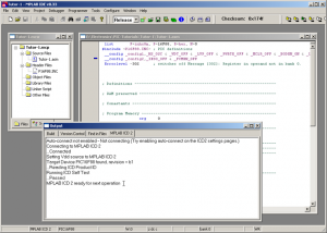 When you do so, the MPLAB IDE will try to connect to the hardware. If the hardware is correctly installed with the drivers installed, then you should get a connection confirmation to the output window that would look like the one on the left. The above procedures needs to be done only once as long as the project remains open. You do not need to select a programmer and connect every tome you compile the program and you want to upload it to the PIC. Instead, you can go to the following steps. Uploading the program to the PIC 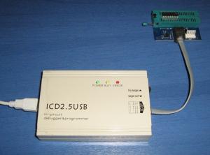 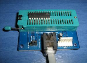 You are just a step away before you have successfully uploaded your first program to your PIC. You can see the images on the left and on the right side that indicates how the PIC is placed on the ZIF socket of the ICD 2.5 programmer. Also, you should have the slide switch to the '5V>Target' position. This position informs the programmer that the PIC is not self-powered (like if it was programed with ICSP) but it needs to be powered from the programmer. If you are sure that everything is as described, then you can go on programming the chip. 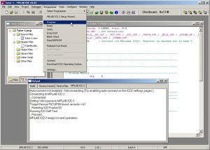 Go to the menu Programmer -> Program 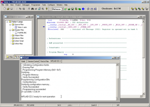 If everything is ok, then within a second the program is sent to the PIC! Congratulations! Confirm your knowledge There is an online test to check your knowledge on this page. You may reveal the test with the following button: Comments
No part of this publication may be reproduced, stored in a retrieval system or transmitted in any form or by any means, electronic, mechanical, photocopying, recording, scanning or otherwise without the prior written permission of the author. Read the Disclaimer
All trademarks used are properties of their respective owners.
Copyright © 2007-2009 Lazaridis Giorgos. All rights reserved. |
  
|
 Contact Contact
 Forum Forum
 Projects Projects
 Experiments Experiments
 Circuits Circuits
 Theory Theory
 BLOG BLOG
 PIC Tutorials PIC Tutorials
 Time for Science Time for Science
 RSS RSS
Site design: Giorgos Lazaridis © Copyright 2008 Please read the Terms of services and the Privacy policy |