This is a very simple and yet useful circuit for generating triangle wave. It can be used for many applications where a medium+ preciseness triangle waveform is required. It can also generate non-symmetrical waveforms making it also useful in audio applications
Another feature that this circuit can provide is that it generates square pulses as well. Although this is not the reason that this circuit is designed and there are much better ways to generate rectangular pulses, you can use them from this circuit as they are in phase with the triangle wave.
Let's see it in action first!
The circuit
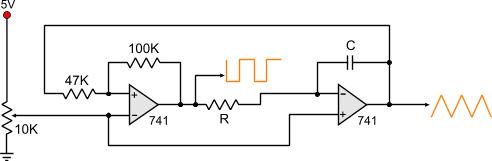
Following is the circuit diagram:
It is designed to operate under 5 Volts, but different voltages can be applied as well, taking in account the maximum operation voltage of the OP-AMPS.
The two op-amps currently used are the known 741 chips. Different OP-Amps can be used as well, and also dual chips for simplicity. The right OP-Amp will operate as an integrator and the left as a comparator. When power is given to the circuit, the comparator drives it's output HIGH. This signal is driven to the integrator through the resistor R. The capacitor C then starts to charge gradually with RC time constant. While the capacitor is charging, the output of the integrator is also taken to it's low state with the same rate. When the positive input of the comparator, through the voltage divider that the 47K and 100K resistors perform, is driven low enough, then it changes state, and the integrator starts operating vice-versa.
It is easily understood that the frequency of oscillation will only have to do with the RC standard. That is true. A half cycle period is exactly the result of the R x C. A full cycle is twice this amount. Therefore, the frequency is:
FOSC =
1
2 x R x C
In our test circuit, the R resistor is 22K and the C capacitor is 100nF. The oscillation frequency would be:
FOSC =
1
2 x 22x103 x 100x10-9
And that would make 227,27Hz approximately. In real life, the frequency measured was about 218Hz. This is a rather small (tiny) difference between the theoretical and the practical value, considering that the resistors have 5% accuracy and so does the capacitor as well.
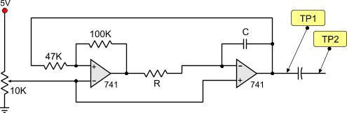
Elimination the DC voltage from the output
If you watch the output signal in a oscilloscope, then you will notice that the triangle waveform is above of the zero voltage. The offset is caused by DC voltage. In order to eliminate this voltage shift, you should add a capacitor in series to the circuit. The value of the capacitor should be chosen accordint tot he oscillation frequency of the circuit. For low frequencies, 1-100 Hz, a 4.7uF to 10uF would work just fine. Above you should consider using smaller capacitors. A wrong capacitor selection would cause signal distortion and sometimes will add significant resistance to the output. The following circuit demonstrates the previous circuit with a series capacitor.
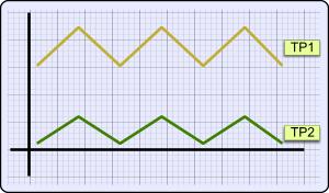
And the results of this circuit are as follows:
As you can see, the waveform right after the capacitor is slightly above the zero voltage, where the waveform before the capacitor is several voltages above, due to the DC voltage shift. Now the output is easier to be used.
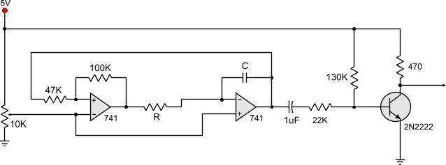
Further amplification
Due to the nature of triangle waveforms and their applications, most of the times the signal should be as high as possible, reaching up to the supply's voltage. For that and to be our circuit presentation complete, we have add a signal amplifier using a 2N2222 transistor. The transistor is connected right after the DC cutoff capacitor (naturally) and is fixed-biased with common-emitter connection:
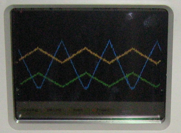
Let's take a look now to the oscilloscope for the results. I chose to show 3 channels simultaneously, all at the same ground level and all with the same amplitude division, so that the differences are clear:
The difference is clear now. The yellow waveform is the output of the integrator. As you can see, the lowest point of the triangle is at about 2.4V above zero, and the highest is at 4volts (1.6V p-p). The green waveform comes right after the DC cutoff capacitor. Almost with the same amplitude (1.4V p-p), this waveform's lowest point is touching the zero line. Finally, the blue waveform. This is the output of the transistor. It starts from zero to 5 volts (5V p-p). Notice also that this waveform is inverted in comparison to the others and that is because the transistor amplifier is an inverting amplifier.
Now that you know the outputs, you can choose the circuit of your will!
Adjusting the circuit
Generating non-symmetrical waveforms
Adjusting the circuit without an oscilloscope
How to get one channel of your old PC speakers jack and use it as a probe
You may have already notice this tricky trimmer on the bottom left corner of the circuit. This is the symmetry adjustment. It is most possible the the circuit will not oscillate by the time you power it on!!! That would be normal. You need to adjust the symmetry at first.
If you have an oscilloscope, the symmetry can be fine adjusted with a straight-forward method. Just put your probe on the integrator or the transistor output and turn the trimmer, until you get a nice triangular waveform. You may also like to have a saw-tooth like waveform, right edge or left edge. This can be adjusted by the trimmer. For large changes, you should consider changing the 47K resistor, otherwise the circuit shall not oscillate.
You should connect the speaker channel right after the DC cutoff capacitor
For those who does not own an oscilloscope, i have some good news. A pair of PC speakers would be your probe for the moment. Connect one channel of the speaker right after the capacitor and the ground of the speakers connect it to zero. DO NOT CONNECT THEM AFTER THE TRANSISTOR OR BEFORE THE CAPACITOR! I could not predict the results. Then, turn them on with the volume at 1/6. Start rotating the trimmer. According to the oscillation frequency that you have chosen, you will hear an audio signal like a "beep" or "booooooo" or something similar. Continue rotating the potentiometer. The signal will become louder and louder. After a while, the signal will start loosing intensity and become weaker. The position where the signal had the loudest sound, is the one that the triangular waveform has the most equal-sided form.
A last trick
The rectangular pulses are NOT inverted in comparison to the triangular waveform taken from the transistor inverting amplifier
It has been already mentioned that this circuit can generate rectangular pulses as well. This is not the reason of creation though. There are better oscillators for this reason. Nevertheless, if you need square pulses in phase with the triangular waveform, the circuit can provide these to you.
The rectangular pulses are taken directly from the output of the comparator OP-Amp. That would be the left one in our circuit. The pulses have almost the same amplitude as the power supply. They have just a little bit voltage shift that most of the times does not cause any troubles. If there is a problem, a DC cutoff capacitor will solve it.
You should keep in mind that the rectangular pulses are inverted in comparison to the triangular waveform. This mean that when the triangular waveform is at it's most high level, the rectangular pulse is reaching zero and vice-versa. But if you compare them to the triangular waveform taken from the transistor amplifier, then you will notice that they are NOT inverted, and that is because the transistor performs an inverting amplifier.
I have been looking for a way to replace the transistor output stage with an op amp. I know I could mess with the gain to get full voltage, about three looks close; but I would prefer that the output stage be proportional without needing adjustment.
iam so frustrated Because every time i trying to fix my circuit,i get more frustrated and iam not getting succeed.
can you please give me a schematic that works properly with LM393?
At 30 March 2014, 12:27:37 user ram wrote: [reply @ ram]
guyz help me to build a circuit to convert 230v ac to 230v triangular wave
Pls I need to build a 5000-6000Hz triangle wave oscillating between 0 and 12v(peak to peak is 12v since that is the supply voltage).
With so many people complaining am confused as to which transistor I should use so as to ensure that the triangle is perfect.
I am using R= 10k and C= 10nf.pls any advice on the transistor amplification so that the triangle does not get skewed or something.
I need it to be perfect 12v peak to peak.i don't have an oscilloscope so it makes my work harder as I would have experimented myself but maybe someone has tested and confirmed it.thanks
Thank you very much for the triangular wave generator circuit. It works perfectly well. I've been trying out other circuits I got from the internet as I needed to use it for a switch-mode power supply (my first ever) & they didn't work, except for yours which produced such incredibly clean waves I was more than amazed. This post is simply to say thank you for your efforts, they are extremely appreciated by myself Mr Giorgos Lazaridis.
By the way, I used a clamping diode, connected to the capacitor, and a diode and high value resistor between capacitor and output. Now i have a perfect triangle, going from -0,3 to 4,95V.
Hi, you probably have VCC hooked up to the voltage divider.
VCC needs to be connected to the full 5V, VCC- to ground.
Input- of the left opamp and input of the right opamp need to be connected to the voltage divider, meaning 2,5V.
Do you have a picture or sketch of your circuit?
Greets!
K
At 3 July 2013, 12:21:17 user Ems wrote: [reply @ Ems]
I've tried building the circuit on a breadboard but it doesnt oscillate at all. I have a steady 2.5V output. I'd appreciate any suggestions as to where I'm going wrong. Many thanks
@Kboy Going negative is normal because you probably use big capacitor. Try a smaller one - say 470 nF...
At 16 June 2013, 14:43:34 user Kboy wrote: [reply @ Kboy]
@Giorgos Lazaridis
Not exactly... without capacitor it floats around 6,5-7V with the same 5V amplitude. I'll try with a 2N3904 or F245C tomorrow. Or are there other options?
I didn't want to use a transistor actually, but if it seems to be the only solution, oh well, so be it. :o)
I just don't understand why the voltage can go negative after the capacitor...
@Kboy Since you use a rail to rail, try without the capacitor. It gos 0 to V?
At 16 June 2013, 9:53:55 user Kboy wrote: [reply @ Kboy]
Hi,
Lots of thanks for this tutorial. very helpful.
I'm just having one problem:
I built this circuit with a TL082 rail-to-rail op-amp.
The purpose was to make a 25kHz triangle wave with an output going from 0 to 5 volts. I tried that with a 12V computer PSU as a source.
Everything looks great and is working, but with a capacitor in series with the output of the 2nd op-amp (trying to create a wave like the green one in your scope), the triangle wave goes from -2,5V to 2,5V instead of 0 to 5V... I've rebuild it over and over again with different resistors and all, but to no avail.
I'm lost here, I don't understand. Am I doing something wrong?
I love this site and you huys are doing a great job.
I am using NI Multisim to simulate this circuit. but i can get it to oscillate. All i have is a single line as my output for both OP AMP. Please i need help. if you have a copy of this circuit that has been simulated via multisim or any other simulator, can you send it via my mail....so i can see where i am missing something.
Believe me, i have tried every suggestion made on this comment page....
Thanks for your kind response.
I would like to thank the author of this tutorial! Thank you! Great tutorial that I will have good use of.
One question though. Say that I use two rail to rail OP-amps instead, and remove the transistor with its bias resistors and capacitor. After that I change the 47k resistor between the two OP-amps to one just under 100kohm, say 82k.
Wouldn't that increase the amplitude of the triangle wave coming out from the second OP-amp close to the 5V input? Thus giving closely the same result as using the transistor?
@Kali simple 555 can go to 300KHz. Use a CMOS 555 to go higher.
At 16 October 2012, 5:11:32 user Kali wrote: [reply @ Kali]
@Giorgos Lazaridis
thanks for your prompt reply. Could you please suggest any circuit or IC which can generate 500khz square wave? Can ic555 timer generate that particular signal?
Thanks for a very well described circuit! I am wanting to slowly light a LED, ramping up from "off" to full brightness, and back down again, over and over...
I want a full cycle to be quite slow, say 15 seconds to light, and another 15 to dim again. My questions are:
- will the RC values be outside what the chip/circuit can handle? I believe there are max/min values for these and such high RC values may be outside the acceptable values.
- will the output allow me to drive several LEDs? They will be high intensity ones, drawing 30mA each, and I plan on having 9 of them (there is a specific reason for being 9). Now, 270mA may require a slightly higher rated transistor if I want it to run cool, but the bigger question is whether the design will actually allow me to drive 9 diocese?
Of course, each LED would have its own current limiting resistor.
hi,
i put this in falstads simulator, leaving C as 1uf and R as 10K. however i left the right non-invert connected to gnd not the pot and i got a better triangle than with it connected to the pot! (not sawtooth)
Hi, thanks for this.
I would like to connect an LED to the circuit that pulses at the frequency of the triangle wave. However, when I connect an LED between the wave output and ground it prevents the circuit from oscillating. Is there any way to achieve this?
Much Appreciated.
At 20 November 2011, 19:20:48 user josh wrote: [reply @ josh]
yes pure triangle waves Are not an option on any of my synths. I've been looking to get into exsperimenting with pure triangle waves.
@dieter the bese-emitter voltage do not exceed the 0.6-0.7 volts depending on the transistor voltage. The parameter Vbe you refer to is the maximum reverse-biased voltage that the transistor diode can handle. You may not reverse-bias a 2N2222 with higher than 5 volts
ok, thanks for all the help
This will give a a good base to further develop the circuit.
One last question, the 5V emitter base voltage, is this the voltage applied to the base, thus coming from the comparator signal, or is this the voltage on the emitter which means a negative 5 volts?
I ask because in the term BVeb and also in your description the emitter is mentioned first.
@dieter unfortunately i am not the best one to tell you about transistors, i will try though. I googled and found that 2n2222 can be substituted with the BC337, 2N4401 and 2N3904 (attention because it has different pinout), Here are some specs that you need to take into account:
First, the Base, open emitter and collector voltages must be sufficient for your application. As you need 5 volts, most transistors are ok. The collector current (Ic) must be enough to drive your load. 2N2222 can handle up to 800mA. The power dissipation must be able to handle your load. 2N2222 handles up to 500mW.
The above parameters have to do with the power of the transistor. One important parameter which must be near the same is the current amplification, usually shown as hfe. 2N2222 has around 75 so your transistor should not exceed 100 hfe.
Looking at the square graph and presuming that the scale of the oscilloscope presenting the square also is set to 5 volts, it's quite safe to say that the low voltage is about 1,25V.
It touches the first line which is 1/4 of 5V.
So this is quite ok.
The 2n2222 transistor is not for sale here and i wonder if you know which other models would be a good replacement.
I looked at transistor specs and I am not sure which values should match or be close to the 2n2222's? Could you provide me with some properties the transistor should meet in order for me to make a proper choice?
We can rule out breakdown voltage limits since they are always higher then what this circuit is powered by so it will come down to other voltage and several current requirements. I am correct?
@dieter i do not really remember what the "low" voltage was, but i can tell you from my picture of the oscilloscope, that it must be around 2.5 volts. Look the picture with the 3 lines. The blue is the 0-5 volts and the yellow is the output of the circuit, before the capacitor. The green is after the capacitor. I think that i had the same volt/div selection for all channels, and also i had the 0 line for all channels aligned, otherwise this picture would not have sense. So, i can safely assume that the low voltage for the yellow line is close to 2.5 volts.
It is certain that if you directly drive a mosfet it will not work as expected. You need to add a transistor to scale the voltage to the levels you want.
unforunately not, my power supply is a car battery with a steady 12,4V when under load.
After some study into opamp characteristics and especially the 741, I came to the conclusion that, due to the design, it simply is not possible for the 741 to produce a negative signal out of only a positive current.
With me, my oscilloscope sais it does so it has to be my oscilloscope, soundcard, measuring wires or anything other then the circuit itself otherwise I should have a magic or faulty 741 installed.
This is exactly what you say now so it's quite a relieve not to have to break my head anymore over what is wrong with the circuit.
The square wave, according to my scope also forms around the 0v line which is an impossibility so it simply has to be the measuring equipment.
It's time for a real scope.
Another thing, When you put the triangle through the second comparator to produce the square pwm signal, what is your voltage of the low 'off' part? commonly as I read it should be around the 1.8V.cis that correct?
my purpose is to use it as a function generator to drive a power mosfet and as I read in the specs the threshold voltage lies around the 2.1V minimum, so if the off time voltage of the wave is around 1.8V, the mosfet still should be fully closed.
Can you confirm this from your experience?
@dieter aaaaa now i understand what you mean. You mean that the output of the op-amp is a signal around the ground correct? Are you using dual power supply, like for example +12 and -12, or single (like for example +12 and 0)? A signal around the ground is not possible with single power supply. It could be also a setting on the oscilloscope, like for example a setting for AC or DC signal in the input.
Yes, I already thought so about the transistor. It's the first time I work with them, mosfets seem to be less sensitive.
But the transistor doesn't explain the signal forming equally around the 0v axis instead of above.
This signal was the outcome of the basic circuit WITHOUT transistor and extra capacitor.
As far as I know, with the basic circuit it shouldn't even be possible to create a signal in the negative?
I checked the connections over and over again, and rebuilt the circuit several times, everything is ok but still, nothing changes.
The only option I can think of is the influence of my oscilloscope perhaps.
It is a sound card version, I made the wires myself using a coax and two resistors to reduce the voltage. Whatever voltage I use in the wires however, this doesn't change anything.
This really puzzles me.
Apart from the transistor which isn't built in , what could cause the +V -V signal in the basic circuit you think?
@dieter probably the transistor is dead. You must be careful when prototyping with transistors. The base resistors must never become too close to zero, I burn transistors myself this way. To avoid this, whenever i am not lazy, i put a small resistor (like 220 or 330 ohms) in series with the pot, so that if i accidentally go to zero ohms, the current will not exceed maximum.
Moreover, there are situations where transistor biasing require very fine turns on the potentiometer. If this is the case, you may try to change the 470 resistor connected at the C of the transistor. Be careful not to put a smaller resistor than 150 ohms there.
I haven't placed the 130K and transistor yet. The +12v -12v triangle as described forms as result of the basic circuit with only the 47k, 100k and R between the opamps and the capacitor as shown in the very first schematic on this page. strange.
I added the transistor circuit today using a fixed 120k resistor. It gave a signal, also around the 0 volt line.
After building in a pot I wasn't able to get a signal at all and when put back to the fixed resistor configuration it remained dead. Are transistors easily damaged? the only explanation i have for the transistor circuit to stop producing a signal.
@dieter obviously you have to change the polarization of the transistor amplifier. Do this by changing the 130K resistor. Put a potentiometer instead. When you set the pot and you have the output you want, then you can replace the potentiometer with a resistor (measure the resistance of the potentiometer).
I have built this circuit because in combination with the dc-controlled comparator and a variable resister in the opamp circuit, I hoped I was able to get a frequency and pwm controlled ttl-look alike circuit. This is exactly what I was looking for.
It works well except for 1 major difference between the result of your triangle circuit and mine: the triangle forms around the 0v axis, so from - 12v to +12V, I used 12V instead of 5, however, with 5V I got the same results.
I used the exact same components and the basic circuit so without the extra capacitor and the transistor with resistors.
I did change the value of the capacitor over the integrator and used a variable resistor for frequency's is the range of 3-9 kHz.
These do not change the character of the wave I presume, only the frequency.
I really need this wave with its lowest point on the 0 volt line as you have, but I have no idea how to do this or what to change, I am quite a beginner in this area.
Theoretically there shouldn't be a need to change anything at all, but practically there obviously is.
I checked everything a dozen times but it is exactly as you 'prescribed' here on this page.
Do you have any idea's to what might have gone wrong?
MST, you will need to work with a high voltage transistor like NTE175 or similar. I cannot tell you more details unless i test it myself, as working with such voltages is dangerous.
At 24 January 2011, 21:15:39 user MST wrote: [reply @ MST]
How to get the triangular wave with amplitude 245V or 250V? Because I want to compare the triangular wave with sine wave of amplitude 240V to produce Pulse Width Modulation. Please advice. Thank you in advance.
At 19 January 2011, 12:25:06 user Milen wrote: [reply @ Milen]
Yes Kammenos,
I plan to drive a DC motor but I think that PWM has to reach 0V in order to sithch the open collector transistor. I hve trnasistor BD241 and I plan to drive the motor trough it. As after I will need to drive the motor in both directions of rotation I will need to do it trough H-Bridge LM298.
Do you think that after the transistor or the H-Brigge I will have PWM going dowin to 0V?
Because I think that if the PWM does not go to 0V I will be not able to full use the capacity of the PWM speed regulation method.
Milen, 741 is normal to have this offset, and cannot become 0. Only if you had a negative supply as well (eg. +5 -5). What do you want to drive with this PWM anyway? A transistor switch will solve you the problem 100% (which is no problem at all). Do you plan to directly connect something on the 741, like a motor?
At 18 January 2011, 21:18:55 user Milen wrote: [reply @ Milen]
Hello Kammenos,
Triangle wave at the colector of 2N2222 is quite a lot improved after tunning the transistor biasing. By using two potentiometers I found that R130 kohm has to be changed to 100 kohms and R22 kohms has to be changed to R10+R4.7 in series.
But the problem with the PWM at pin 6 of the third 741 still can not be solved. No change is observed.
The bottom edge of the wave still stays at 1.8 V and does not want to change at all. This is not acceptable for PWM wave.
I think that this is some problem with the third 741 op amp. What ever you do it always stays at 1.8V bottom edge.
You can see the pictures here:
http://tinypic.com/view.php?pic=dvouuh&s=7
http://tinypic.com/view.php?pic=1z4eb80&s=7
Do you have any idea how to make the PWM to reach 0V at the bottom?
Thanks!
At 18 January 2011, 11:48:06 user Milen wrote: [reply @ Milen]
Thanks Kammenos,
I will try itonce I am back from work and sure that i will let you know the results.
The Rb is correct. Just to be sure, add a small resistor (like 220 Ohms) between the Rb and the power supply (so it never becomes 5V).
As far as the 4K7 pot, you do not have it correct. Remove the wire from the pot to ground. As a matter of fact, for this potentiometer (which will be connected actually as a rheostat), only the 2 connections will be used, the middle and one other (does not really matter which). The middle will go to the base of the transistor (like the one from Rb - as you have it now), and the other will go to the capacitor. Tell me the results of this.
At 18 January 2011, 10:37:14 user Milen wrote: [reply @ Milen]
Thanks Kammenos for your support!
Actually I am beginner in this field. I heve prepared two pictures which you can see in the following links:
http://tinypic.com/view.php?pic=2vs1aud&s=7
http://tinypic.com/view.php?pic=6sxvns&s=7
Is this the righr way to connect the potentiometer (100 kohms) like voltage divider on the place of the current 130 kohms resistor?
Can I use also similar potentiometer of 4.7 kohms on the place of current 22 kohms resistor in order to be more flexible in tuning the transistor?
If this on the pirture is a wrong connection of the potentiometer, please tell me which pin of the potentiometer where to be connected?
Ok Milen, i got the point. What you really need to do is change the biasing of the transistor. I use one 130K resistor and a 22K to bias the base, while you should use a voltage divider with a potentiometer (for test of course and then replace with resistors), so that you can transfer the Q. Do you know how to do this?
BYV 26E is fast but has forward voltage typical to 2.5 volts. The 1N4148 has typical 0.75 to 1. The best solution of all would be a shottky diode, with less forward voltage. 1N5817 for example has 0.35 drop.
If you have a potentiometer like 100K, try to change the transistor bias. In that case, keep in mind that you may need to decrease the 22K resistor. The must also be much decreased, something like 1K or 1.5K is a good start.
At 17 January 2011, 21:09:19 user Milen wrote: [reply @ Milen]
Hello Kammenos,
I tried it to put diode immediately after the 1uF (between the capacitor and the 33 kohm resisistor). I have diode BYV 26E (could I use this one?) which is supper fast one. But with this diode I got a stright line voltage of 5.6 V (circuit supply voltage is 6V) at pin 6 of the third 741 where the PMW has to appear. I have UA741CP chip.
My prblem is that I can not get PWM signal going down to 0V as it has to be, but I have 1.8V at the bottom edge of the PWM signal as on the picture here:
http://tinypic.com/view.php?pic=2zex8op&s=7
Would you please suggest some other solution or I realy have to try with 1N4148 diode?
Milen, try to add a diode in series, right after the capacitor (anode connected to the capacitor). It will cause a slight voltage drop. For example, 1N4148 will drop some 0.7 volts. You can choose another resistor for smaller drop, but i do not think this will be necessary. If you have problem with the switching speed, use a faster diode (again i think 1N4148 will be fine).
At 15 January 2011, 22:20:12 user Milen wrote: [reply @ Milen]
Hello Kamennos,
I bought a breadboard and assembled the circuit on it this is the full circuit for the PWM generation with voltage control. The circuit now oscillates properly. The problem is that after the 1uF electrolytic capacitors I still have 0.3 0.35 V of DC voltage and I can not remove it. I changed the capacitor with to 2uF and to 10 nF but still the same. It is the same situation at the collector of the 2N2222 transistor where I have 0.6 0.7V DC.
I run the circuit with supply voltage of 4.5V. The resistor r is 4.7 kohms and the capacitor is 100 nF as I target 1 kHz of frequency.
I have put some pictures at the following links:
http://tinypic.com/view.php?pic=jsir2r&s=7
http://tinypic.com/view.php?pic=v45e8x&s=7
http://tinypic.com/view.php?pic=ofzlgk&s=7
http://tinypic.com/view.php?pic=6gkgfo&s=7
http://tinypic.com/view.php?pic=fdyb20&s=7
http://tinypic.com/view.php?pic=iolp9v&s=7
http://tinypic.com/view.php?pic=2zex8op&s=7
Would you please have a look on them?
I do not have oscilloscope and I use National Instruments board NI6008 which cam sample max at 10 kHz at the analog input channel. That is why the triangles and rectangles are not with well described shape.
Would you please advise me how to solve this issue?
Thank you very much!
At 14 January 2011, 16:42:02 user Milen wrote: [reply @ Milen]
i thought that you had a prototype on a breadboard. you have solder the components, i cannot see them how they connect each other. i strongly suggest to get yourself a couple of breadboards. it is super easy and simple for prototyping. plus, there is no way to make error during soldering.
At 13 January 2011, 21:55:05 user Milen wrote: [reply @ Milen]
Hello Kammenos,
I did not find the way to upload the pictures in the forum.
I put them on the followin links:
http://i52.tinypic.com/16lkyms.jpg
http://i51.tinypic.com/acr2f8.jpg
I have more op amps 741.
Actually I am using UA741CP. And for capacitor I use WIMA MKS 4 0.1/400-X1.
Do you think that any op amp could be faild?
Thanks!
3/4 of a turn is ok. do you have replacement 741? it may be needed.
You can send images to the forum:
http://pcbheaven.com/forum/
At 13 January 2011, 11:06:14 user Milen wrote: [reply @ Milen]
Thank you very much for your response Kmmmenos!
I am sure that it works, but probably I have made some mistake as I am beginner in this field.
I will check it once again and I will send you some pictures.
The trimer that I have put is not that much sensitive. Shall It has only 3/4 turn.
Could you advise me how could i send you pictures so that you can check them?
That is strange Milen. I tested the circuit again, from a scratch, following the schematic line by line, like i saw it for the first time. the circuit worked for me immediately after putting some power. with the RC you chose it oscillates at 1.05 KHz. what i can do for you is send me some close photos to inspect it.
Check out this link:
http://pcbheaven.com/temp/video.avi
and
http://pcbheaven.com/temp/image.jpg
Make sure that you have the potentiometer adjusted. Otherwise you get the dead's heart beat line.
At 11 January 2011, 20:33:23 user Milen wrote: [reply @ Milen]
Hello,
Thanks for the good theory, video and explanations!
I created this circuit for triangle wave generation, but I also have a problem - the circuit doess not oscilate and I get a stright line of constant voltage. I use 4.5 kohms for R and 100 nF for C targeting 1kHz of frequency. I have also conected pin 7 of the op amps to the DC 5V and pins 4 to the ground as I had forgotten this in the begining, but still I can not make it oscilate.
Would you please advice me what could be the reason?
Remark 1. The potentiometer you have seems that the negative is in the wrong track. It is not clear but i think it should be connected one hole above.
Remark 2. The 2nd 741 (right) has no ground (pin 4)
Remark 3. Confirm that yellow cable from pot goes to pin 2 of left 741
Make these corrections and if not work, post some new photos. Please get some also from above (do not put part values).
Get some detailed photos from the circuit you\'ve done. I prefer clear close photos where the parts are shown clear. Then make a new thread in the forum (http://pcbheaven.com/forum/) and post them. I will be notified automatically, no need to notify me. Do it and we will continue our conversation there.
Did you try to adjust the 10K potentiometer? You need to make slow steps. Put the oscilloscope directly to the output of the 741. Do you get at least rectangular pulses to the first 741?
Looks like that the transistor base gets too much current. Do you use 1uF capacitor or you have 10? It must be 1uF. If it is 1uF, then try increasing the 22K resistor at the base of the transistor. I recommend you use a potentiometer (50K for example) in series with a 10K resistor. That should do fine.
At 2 November 2010, 21:01:34 user Ricky wrote: [reply @ Ricky]
Kammenos, thx for your help =) I almost got the triangle wave (0V-5V), but the output is satured and almost square. Some way to solve it easily?
Ricky, in the 3rd circuit there is an amplifier transistor stage at the end (2N2222). At this point, you should get an amplified signal at the collector. Measure at the point where the 470 ohms resistor meets the 2N2222 C connector. You must have 5 volts signal. Use 1uF capacitor for the interface of the base of the transistor. try other transistor if it does not work. It would help a lot if i see pictures from your oscilloscope. Upload them in our forum (http://pcbheaven.com/forum/) and give the link here.
At 2 November 2010, 6:46:41 user Ricky wrote: [reply @ Ricky]
I\'m havng problems with the offset and amplifier circuits... I want to do a 1khz oscilator (0V to 5V), so I use R=5k and C=0.1uF.
The problem starts wehn the signal pass by the first cap. I tried a 10uF for this circuit, but the output stay between -1V and 1V.... When i tried to use the 3rd circuit the output wave is almost a DC wave... I don\'t know how to fiz it. Can you help me?
At 28 October 2010, 17:54:31 user nawras wrote: [reply @ nawras]
i need some help in my project is about digital function generator
con any one help me
use the 3rd circuit with the transistor amplifier. Power the transistor with 10 volts instead. Keep the oscillator at 5 volts to operate. You may need to change the 3 resistors that polarize the transistor, but you better put an oscilloscope to see the results.
At 28 October 2010, 9:19:46 user Wimbo wrote: [reply @ Wimbo]
Hi,
when i try to eleminate the offset the triangle wave goes below 0
I want to compare it to a 0-10V signal, So i also need a triangle 0-10V
any help possible? Thanks
At 13 October 2010, 15:31:55 user Capn wrote: [reply @ Capn]
I cannot get this circuit to operate properly. I have modeled it using NI Multi-sim, and I only get one cycle out of this configuration before it goes flat.
Are you using a DC input? Or are you putting some AC signal to the supply?
thanks that really helped.
will the output be in the form of impulses if instead of a triangle wave, a sawtooth signal was applied at the input of the 3rd opamp???
I suppose that you made a PWM generator with DC voltage duty cycle selector. I have a similar circuit here:
http://pcbheaven.com/circuitpages/Voltage_Controlled_PWM_Generator/
You can remove the 2N2222 amplifier along with the 3 biasing resistors, and then you have exactly the circuit you described. Read the theory from there, and also you can read the theory for PWM here:
http://pcbheaven.com/wikipages/PWM_Modulation
I have done a practical like this one at school. but the output from the 2nd op amp was compared to a DC voltage using a 3rd opamp, followed by a capacitor. impulses were obtained at output. i don't understand the theory. could you please help me with that....:)Thanks
Using the formula that i give with 0.1 uF capacitor:
For 1KHz: R = 5 KOhm
For 10KHz: R = 500 Ohms
So, use o.1 uF capacitor for C, and 470Ohms resistor in series with a 5K potentiometer for R. Then you need to test because theoretical values may differ from real.
At 1 September 2010, 14:25:10 user kenlee wrote: [reply @ kenlee]
hello.....can u give me some idea or circuit diagram to determine the ranges of 1khz - 10khz only?
At 4 August 2010, 7:16:53 user libz wrote: [reply @ libz]
ok2 thank you. . .can we ask another schematic diagram for square and triangular waveform generator ranges the output from 1 khz - 10khz?
Also, I started with an op amp for the comparator, and after testing changed to an actual comparator to get cleaner (more vertical without slew) switching.
The maximum frequency for 741 would be around 10KHz. Are you trying a higher frequency? You may consider changing the op-amp. Try also to change the capacitor
I am getting a spike at each peak of the triangle wave.
Why?
How to eliminate that?
Am I doing something incorrect?
At 16 February 2010, 21:08:27 user Nikos wrote: [reply @ Nikos]
Thanks for the info guyzzz!
I am in middle of an assignment currently, and i really need two such generators in my board, though I must make them sawtooth.( I may have some ideas)
I was trying similar configuration using op amps, for the triangle wave, but I found yours more suitable. Especially the part with the variable resistor.
you can use a transformer to drop down to 12 for example, and then a voltage divider to drop it to 3 volts, and measure this with the A/D converter of the PIC
Hello Dennis,
This is perfectly normal because the 2n2222 is biased for 5V. Above 5V the transistor operates in saturation, and this causes the one side of the triangle to become straight.
As for the bending, i suppose that it comes from the capacitor. What capacitor you use? Try 100 K resistor (R) and 0.1 uF capacitor (C) instead of an electrolytic capacitor. If it works, please post the results for us to know!
Hello S L Lau,
The max frequency for this circuit is around 10KHz. You could increase this number by using another op-amp, but i am not sure about this
At 17 December 2009, 12:04:56 user Dennis wrote: [reply @ Dennis]
Why is it that at at voltages beyond 5V it produces a trapezoid instead of a triangle? Also why is it that at 50hz frequency one side of the triangle wave looks bent? Please advise me on how to change this circuit to produce a clean triangle wave of 50HZ at 13V. Thanks
Hi,
I have one question here. Is there any restriction to the max frequency that can be achieved? I only managed to get a max of 8khz and it start to distort. Please kindly advise.
I really like the way you present the circuits and the 'Modular' way you put them.
I began from the 'Ambient Light Controller', that needed the 'Voltage Controlled PWM'. The Voltage Controlled PWM needed the 'Triangle Wave Generator' and that lead me here. I like the way you are presenting them.

 Home
Home
 Projects
 Experiments
 Circuits
 Theory
 BLOG
BLOG
 PIC Tutorials
 Time for Science


 Contact
 Forum
Forum
 RSS
RSS


 Reddit this

