When someone learns about the Schmitt trigger, i believe that a thermostat is the first application that comes into his mind. The Schmitt trigger works exactly as a common thermostat would do. If the temperature exceeds a specific point - the "High threshold", it will arm a relay until the temperature falls below the "Low threshold". The difference between high and low threshold is called "hysteresis". The only difficult thing is how to choose the right components as there are many parameters. This circuit is an implementation of a thermostat with a Schmitt trigger. I will show you how to make one, and how to choose the correct component values to change the settings of the thermostat: High threshold, Low threshold and Hysteresis.
The circuit
First of all, i will show you a circuit that i made for my PC cabinet. The circuit can be adjusted from 22.5oC up to 50oC and has a hysteresis of around 2oC. If for example the circuit is adjusted to 30oC, the relay will be armed when the temperature exceeds this point (30oC), and it will be disarmed when the temperature falls bellow 28oC (30-2).
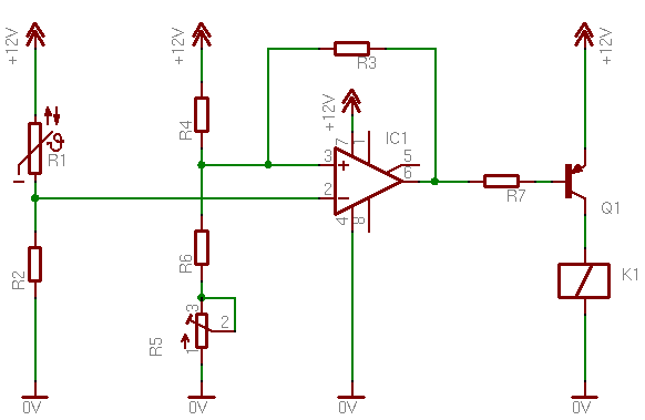
So, let's see the circuit:
Starting from R1 and R2, this is the temperature measuring twin. R1 is a 10K NTC thermistor. Along with R2, they make a voltage divider. The voltage output of this divider will change according to the temperature change. This voltage is then driven directly to the inverting input of the 741, a normal configuration for a single power supply Schmitt trigger using OP-Amp. The output of the 741 drives the PNP power transistor. The output is reversed and the load is directly driven from this transistor.
As i said before, the circuit can be adjusted form 22 to 50 oC. This means that when R5 is turned completely to the left (0 ohms), the load will be actuated above the 22oC, and when it is completely right (max resistance) it will be actuated above 50oC. I chosen these values because i plan to install this circuit in my PC cabinet. This range will fit my needs. Nevertheless, i will explain how you can select parts yourself, in order to change the range and hysteresis at your will.
Can i change the relay with something else?
The circuit was originally designed to control a fan. The transistor can handle up to 600mA load
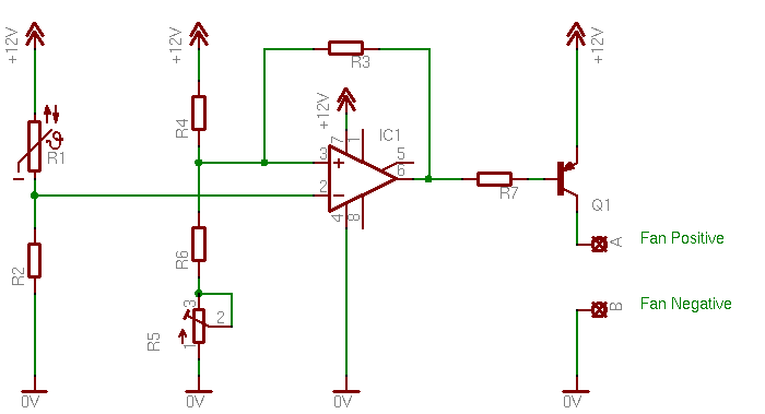
Well luckily yes, you can. I used the 2N2907 that can handle up to 600mA. So, you can simple remove the relay and instead put a 12V buzzer. Or better, you can put a PC fan! Well OK, you got me! This is exactly what i had in mind from the beginning of this project. Usually, PC fans will not draw more than 350mA. This is about half of what the transistor can provide, so a PC fan can be easily controlled. Just remember to put the positive wire of the fan on the collector of the transistor, and the negative to the ground, like the following schematic:
The positive goes to A and the negative to B. Same is if you use a buzzer that has polarity! Positive to A and Negative to B
Bill Of Materials (First circuit)
Resistors
R1
NTC 103 10 KOhm NTC Thermistor
R2
Resistor 4.7 KOhm 1/4 Watt 5% Carbon Film
R3
Resistor 100 KOhm 1/4 Watt 5% Carbon Film
R4
Resistor 5.6 KOhm 1/4 Watt 5% Carbon Film
R5
5 KOhms potentiometer
R6-7
Resistor 2.2 KOhm 1/4 Watt 5% Carbon Film
Integrated Circuits
IC1
LM741 Operational Amplifier
Transistors
Q1
2N2907 General purpose amplifier and switching transistor
Set different temperature range and threshold
I have to warn you that this is a little bit stiff if you do it for the first time. If you are not interested in changing the setting of the above circuit, just skip this step.
First of all, you need to know some more details for the thermistor. You need to know actually, how the resistance changes in relation to the temperature. Luckily, i had ran an experiment with this thermistor. You can find this experiment here. I discourage you though to run such a detailed experiment yourself. Instead, you need to make sure that the thermistor you have changes linear. If it is not, then you will probably fail to calculate the circuit. You can have this info from your thermistor vendor.
Then, you need to know the resistance of the thermistor in room temperature. This value, corresponds to the resistance of the component when the temperature is 25oC. You can also learn this information from your vendor. Usually, this info is printed on the thermistor. A 10K thermistor for example (like the one that i use), will have 10K resistance in room temperature.
Finally, you need to know the slope of the change. That would be the hardest part if you are not in a laboratory... What you really need to know is the resistance of the thermistor in another temperature. So, either put it in the refrigerator, or put it somewhere hot. 10-20 degrees above or below room temperature is the place where you should put it. Put your imagination to work. When you do find the resistance in this specific temperature, then draw the characteristic of the thermistor as i explain in the thermistor experiment.
Now that you have the characteristic of the thermistor, you can easily calculate the various resistance values for various temperatures of the thermistor. I explain in the experiment how to use the line equation calculator to do this.
Now it is time to decide the upper and lower temperature limits. Suppose that you want to narrow the temperature settings (and thus increase the stability and accuracy). Suppose that you want to be able to set the circuit from 20 up to 40oC, and the hysteresis about 4oC. First of all, you need to calculate the thermistor resistance value for these temperatures. In my case:
20oC = 12.174 Ohms 40oC = 5.454 Ohms
Now you need to run some tests to find the best R2. The best R2 is the one that will generate the biggest voltage difference for these values, while it will not be too big or too small to cause problems. It should be minimum 1/10 of the thermistor nominal resistance and not bigger than 10 times the thermistor's nominal resistance. In my case, it should be between 500 ohms and 100 KOhms. Use the Voltage Divider Calculator to solve for V2, and speed up the process. I will use a resistor 2.2 KOhm to have a reasonable voltage output. The voltage outputs will be:
20oC = 1.8 Volts 40oC = 3,45 Volts
I want a hysteresis of 4oC. I have to express this value in voltage difference. According to our previous calculations, from 20 to 40 degrees, the voltage difference is 1.65 volts. Thus, for 4 degrees it is 0.33 volts.
Now you have everything to start playing with the Schmitt trigger. You have a very handy tool for this, the Schmitt trigger calculator for single power supply OP-Amp. Each resistor value change will have a particular effect on some values, while on the others they will have only a slight affect. RFB for example (R3 in my circuit) usually changes the hysteresis. Thus, i will use a rather big resistor to have so small hysteresis (0.33V). Thats a good point to start with.
First to calculate R4 R5 and R6. I will start with the minimum voltage level. In that case, R5 is 0 as the potentiometer is fully turned to the left. Use the calculator and fool around until you find some values for those resistors, that - along with R3, will give a V High near 1.8 volts and a V Low about 0.33 volts lower... you need time and experience. The more you play with, the more you understand what is going on. I suggest you use resistor values that do exist. If you do not know them by heart, then advice the Standard Resistor Calculator.
I came up with the following results: R4=10K, R6=6.2K, R3=220K. Possibly you may find other values. That is NOT wrong. They may also be correct. There are many ways to solve an electronic problem, and sometimes this is the biggest problem in electronics. Now for the potentiometer. During this step, you may come to the conclusion that the values you found for the 3 resistors may be wrong. Unfortunately, you will need to calculate resistor pairs... Now, there are very certain potentiometer values. I suggest you try the 1K, 2.2K, 4.7K, 10K, 22K, 47K and 100K. What you have to do is, to add every time the value of a potentiometer to the value of R6. If the result of V High is close to 3.45 volts and the result of V Low close to 3.15, then you are finished. Now let's see my resistor pair... Using a 10K potentiometer i get the following values:
V High = 3.53V and V Low = 2.91 Volts.
Are these values OK? let's see. According to my thermistor experiment, 3.53V corresponds to around 41oC and 2.91 corresponds to 35oC. The High value is ok, the hysteresis is changed too much though. So i have to recalculate the resistors with a larger R3 in order to have less hysteresis. This is the point where you need experience and patience... And some luck.
At 17 October 2015, 20:06:44 user Alvaro wrote: [reply @ Alvaro]
I had to put a 10k resistor from pin 6 to 12v because once connected the transistor will not shutdown.
At 5 November 2013, 15:56:46 user paul wrote: [reply @ paul]
Hi,
I am doing a similar project with a temperature controlled room. I would like to set a Hysteresis of about 5 degrees C between 20-25 degrees C. My circuit would be connected to an oil radiator 240v but I could simulate this if needs be.
but i need a help in my design , I want to put the range between 50C and 100C , But I couldn't find the best R2. and im not sure if this is the design i need for my projet
Here the Question for the design , i wish you can help me :
Temperature is to be measured in the range of T1 (50C) to T2 (100C). The sensor is a resistance (RTD ) which varies linearly from R1 (141%u03A9) to R2 (171%u03A9 ) for this temperature range.
a. Design analog signal conditioning circuit which provides a voltage varying linearly from 0V to 5V for this temperature range
b. Design a circuit to light a LED whenever the temperature is within T(50C) and T2(100C) otherwise the LED is OFF.
At 6 December 2012, 2:19:35 user Gzub wrote: [reply @ Gzub]
Great circuit! Brilliant, in fact. I want to use a 5k NTC thermistor. Would I have to reduce R2 to something like 2.2KOhm in order to have it work just the same as your original circuit?
@Andy I'm sorry Andy but i do not make or change circuits on demand. You will have to experiment yourself following the steps that i took.
At 8 November 2012, 19:16:40 user Andy wrote: [reply @ Andy]
Hello,
I have seen that you have experience with thermostats. I need to replace my refrigerator thermostat (it%u2019s almost just a refrigerator, its `freezer` compartment goes to maximum -5 Celsius). I built this schematic:
It is working well, but only for positive temperatures (20 Celsius to 70 Celsius works perfect). I tried different solutions to make it work to temperatures nelow zero (i use LM35CZ) but to no avail...
Then i discovered this page. Can you please help me with the values that have to be changed? I need a schematic to operate from -5 Celsius to 4 Celsius (to use VR3 as readily-adjustable device, in the range of -5 Celsius 4 Celsius as the old thermostat knob used to do).
I would like to power the design from a 5,1v stabilized power supply (i%u2019d like to use a phone charger as power supply). I think i%u2019m going to use LM211P which works from 5v.
Best regards,
Andy
At 22 October 2012, 0:12:55 user Bill wrote: [reply @ Bill]
Your circuit may be old but being new to electronics I learned a lot by building and studying it. It also seemed like a good example to practice developing the equations for the circuit and calculating "exact" values based on your reported thermistor resistances at two temps.
I calculated the derivative of the voltage diff vs R2 to find the max diff and R2 was 5.85 KOhm (= Sqrt(Product of the thermistor resistances at each temp/2) - which gives output voltages of 3.89V and 6.21V - a greater voltage diff than that which you used (2.32V vs 1.65V) but higher voltages. For a 4 deg hysteresis, this gives 0.464V vs your 0.33V. However, it seems 6.21V is in excess of that required for 40 deg with your thermistor. I wonder if the requirement to maximize the voltage diff for R2 may need adjustment.
But I continued and then calculated R3, R4, and R6 by calculating the minimum difference for the Schmidt trigger using 6.21V and 6.21-0.464V or less as the goal and R5 = 0V. The computations are a little more involved but the derivative of the difference function between the high and low voltages gave R4 ~ 1.01*R6 and R3 ~ 12.4*R4. Taking R6 as 2.2 Kohm gives R4 = 2.2 Kohm and R3 = 40 Kohm. These values produce high and low voltages of 6.16V and 5.84V with a difference of 0.32, even less than the desired value. Values are much less sensitive to changes in R3 than R4 and R6 (R3 = 200 Kohm and same R4 and R6 gives 6.03 and 5.97V).
There is no space to describe in detail how I did the calculations but the circuits involved are relatively simple - R2 is a simple calculation and the Schmidt trigger one is just two variations of a parallel plus serial resistor network.
Assuming my calculations are correct, I am bothered by them not giving values that are near the voltages required for your thermistor, esp since they should produce mathematical minimum and maximum values. I have not used these values in a prototype yet - I need more data for my thermistor. I would appreciate any thoughts you might have on the subject.
Being new to all of this, there may be more art involved than seems on the surface. I know some 10K thermistors I purchased on eBay are generally OK but are not 10K at 25 deg as one would expect. It seems one really does have to calibrate the thermistors one uses.
@Jai oh i see. unfortunately this is a rather old circuit. I do not have the eagle schematic neither.
At 11 October 2012, 15:07:18 user Jai wrote: [reply @ Jai]
@Giorgos Lazaridis i mean when u create a schematic in eagle we can have its board diagram as well, so do you have that diagram which can help me to create my pcb.
@Jai i don't have a pcb layout, i never designed a pcb for this circuit
At 10 October 2012, 14:34:07 user Jai wrote: [reply @ Jai]
Thanx for your circuit. It works exactly as you said. I need a help,as I think you have designed the layout using Eagle software, so can u please send me the PCB layout so that i can use it make actual PCB, as i dont know how to use Eagle.
It was my transistors. I bought two 2n2907A. Somehow I managed to fry them both. Went to Radio Shack and got a package of 15 (276-1604). Worked with the first one I tried. Awesome. Now to move it from the breadboard to the circuit board and home I don't screw it up with my soldering skills. Learned a lot from this website. Thanks.
I'm getting warmer with this circuit. Between R7 and Q1 I am measuring 1.31 volts when the trigger is active and 11.56 volts when the trigger is off. These voltages changes to the base of Q1 do not result in any voltage change between the collector and ground. It remains 12volts regardless of the change in the trigger voltages. Is Q1 bad or do I not have the trigger correct?
http://www.mouser.com/ProductDetail/Murata/NTSD1XH103FPB40/?qs=zqbRmZ%252bfZD%2fzspO32mP94Q%3d%3d Is this the same as your thermistor? I built this circuit with the values listed in (First Circuit) but it never shuts off. It is always on.
Suppose i wanted to turn on a piece of equipment if the temperature falls below 37.5d celcius and turn off above this with a hysterisis of plus or minus 0.5d celcius what value components would i use.
@Marco Oh well, that won't be an easy job to do. You will need to prototype it on a breadboard and do some tests first. And use my online calculator for the schmitt trigger to help in the dr.calculus pages.
Hey! Really nice project. I am planning to make it myself in order to power a cooling pad fan. The only thing is that I would like to power it via USB, an since that means 5V instead of 12V, I was wondering if the same parts would still be compatible. Could you give me a hint about this?
Thanks and great material!
At 11 March 2012, 14:28:20 user neer wrote: [reply @ neer]
hey great circuit thanks for sharing it!!! well m stuck and need help with calculations my thermistor has resistance of about 100ohms at 30'c and i want the fan to come on at about 40'c and hysteresys could be 2-4'c what changes in resistor will i need to make can u do me the calculations and tell as i have no idea about it.(my thermister is ntc100d-9 type).
At 26 November 2011, 19:34:00 user Paul wrote: [reply @ Paul]
Hi what is best values for 50 to 90 degree control using a 10k thermister
@Gon exactly the opposite of what i do now. connect a heater to the NC contact of the relay.
At 19 July 2011, 23:21:39 user Gon wrote: [reply @ Gon]
What would you do if you want to maintain a higher temperature than the surroundings (for example you want to keep the living room at 20 C while it's freezing outside)?
Is that easy to implement?
@ramy this is a thermostat circuit, so the potentiometer's function is to set the temperature where the thermostat output will be HIGH or LOW. It is the same like the thermostat in the air condition or the heating apparatus in houses.
At 16 June 2011, 4:18:21 user ramy wrote: [reply @ ramy]
jefdeal, regarding the voltage divider. The problem is i think that i am not 100% used to the english way of representing numbers. I had some errors, for example the number 12.174Ohms is not correct, it should be 12174Ohms or 12,174Ohms, but not with dot. (i changed it). Use 12174 or 12.174 KOHMS in the voltage divider.
Also i fixed the 500 ohms. You are right, it is 1000. But keep in mind that the 1/10 is a rule that can be changed according to your needs. The 1/10 is just a good start.
This is a very good circuit to start with, is simple in making and hard in calculations. Assemble it on a breadboard and have some different resistor values to change and notice the results. Get a resistor pack from ebay of other supplier, and a couple different potentiometers.
There is a problem with your \\\"Voltage Divider Calculator\\\". Solving for V2 enter these values. V1=12V, R1=12.174Ohms, R2=2.2KOhms. You will get V2 as 11.93. If you change R2 from KOhms to Ohms you will get the 1.8V as specified on the page. I am very interested in modifying this circuit, but this will only be the second circuit I have built. If I am wrong here please explain, otherwise please let me know what must be corrected to allow the R2 value to fall within the 1/10 to 10 times window of the value of the thermistor. Also if you have a 10K thermistor wouldn\\\'t the 1/10 value be 1KOhms and not the 500Ohms stated?
I really do not follow you herctrap. Connecting a NPN instead of a PNP, will reverse the operation of the circuit (of course). If you mean output the voltage between the NPN emitter and the ground, then it will be 12V minus the VCE. This depends on the transistor you use. Check the specifications. The 2N2907 has approximately 0.8V voltage drop for the fan load (less for the relay).

 Home
Home
 Projects
 Experiments
 Circuits
 Theory
 BLOG
BLOG
 PIC Tutorials
 Time for Science


 Contact
 Forum
Forum
 RSS
RSS


 Reddit this

