Home     Contact     Projects     Experiments     Circuits     Theory     BLOG     PIC Tutorials     Time for Science     RSS     Terms of services     Privacy policy  
   
 Home      Projects     Experiments     Circuits     Theory     BLOG     PIC Tutorials     Time for Science   

8 August 2011
Author: Giorgos Lazaridis
PWM LCD Contrast Adjustment


The circuit on a breadboard for test

Most of you probably know the popular HD44780 character LCD controller from Hitachi. Usually you find it on LCD display boards with 16 pins. One of these pins is called "Contrast Adjustment" and does exactly this: It adjusts the LCD contrast. This pin requires a voltage level. If a microcontrollers has a Digital to Analog module, then this pin can be directly interfaced with this module. But the D/A module is not very common, instead, the PWM module is.

In such applications, the backlit is usually done with LEDs, so a simple PWM driver can directly adjust the brightness. Unfortunately, the PWM module cannot be directly used to adjust the contrast. So, i made a very simple and small circuit to interface the PWM output of a microcontroller to the contrast adjustment pin of an HD44780 Character LCD.


The Circuit

Here is the circuit schematic: (click to enlarge)
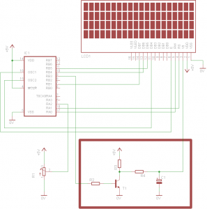


There is a red rectangle at the bottom right corner of the schematic. This is the interesting part. The rest of the circuit (the PIC along with the LCD) is only added to demonstrate the circuit operation. The PIC initializes the LCD and then sends a simple string to be displayed. The potentiometer R1 is used to generate a control voltage from 0 to 5 volts, and it is directly interfaced to an analog input of the PIC. The PIC then translates this control voltage into a binary number with the internal A/D module. Finally, it generates a PWM signal with a duty cycle from 0 to 100% according to the analog control value taken from the R1 potentiometer.

The PWM output from the PIC (RB3) is then driven to the interface circuit. This circuit is composed by a transistor amplifier (T1) and a low-pass filter R3/R4 - C1. This low pass filter will convert the PWM signal into a voltage level. This voltage level is higher when the PWM duty cycle is closer to 0%, and lower when the duty cycle is closer to 100%. This signal can be directly used for the contrast adjustment of the LCD.


The PIC Firmware

 PWM LCD Contrast Adjustment - Assembly listing - V1.0

 PWM LCD Contrast Adjustment - Hex file - V1.0


Bill Of Materials
Resistors
R1Potentiometer 10 KOhm Linear Rotary 1/2W
R2Resistor 22 KOhm 1/4 Watt 5% Carbon Film 
R3Resistor 4.7 KOhm 1/4 Watt 5% Carbon Film 
R4Resistor 680 Ohm 1/4 Watt 5% Carbon Film
Capacitors
C1Electrolytic Capacitor 47 uF 16 Volts
Transistors
T1BC548 Switching and Applications NPN Epitaxial Transistor 
Integrated Circuits
IC1PIC16F88 Microcontroller 
Misc
LCD1LCD 16x2 Character LCD w/ HD44780U1 controller 


Comments

  Name

  Email (shall not be published)

  Website

Notify me of new posts via email


Write your comments below:
BEFORE you post a comment:You are welcome to comment for corrections and suggestions on this page. But if you have questions please use the forum instead to post it. Thank you.


  • At 10 August 2015, 2:33:21 user Nicole Liang wrote:   [reply @ Nicole Liang]
    • It seems interesting


  • At 22 March 2014, 16:12:41 user Giorgos Lazaridis wrote:   [reply @ Giorgos Lazaridis]
    • @jon Oh didn't I??? I'm afraid you have to find it yourself. It should be around 1 to 5KHz, not really matters...


  • At 15 March 2014, 15:00:00 user jon wrote:   [reply @ jon]
    • Hi Giorgos,

      You didn't mentioned the PWM frequency. In the Youtube comments you mentioned that you tested with 16.2KHz but I doubt that this is the final frequency.
      Yes, I know, I'm too lazy to calculate it from the source code...


  • At 9 February 2012, 10:31:47 user Giorgos Lazaridis wrote:   [reply @ Giorgos Lazaridis]
    • @Sajjad no problem with PWM and ADC for me. What do you control with the PWM? And what sort of spikes? You have oscilloscope view? Post them in the forum to see


  • At 9 February 2012, 9:05:07 user Sajjad wrote:   [reply @ Sajjad]
    • Have you ever encounter a problem that your PWM pulses are affecting your ADC, i am stuck in such a problem. for every rise and fall, spikes appears on my ADC pins. PIC = 16f877A


  • At 8 August 2011, 22:08:58 user Kammenos wrote:   [reply @ Kammenos]
    • @_pike as a matter of fact, the problem with the LCDs is not the ambient light but the ambient temperature. Brand LCDs come with temperature coefficient, and you make a circuit that changes the contrast according to the temperature.
      As for the LCD backlit, this circuit could be used but it is not efficient. A Simple PWM circuit or a simple transistor amplifier on one of the PWM outputs of a PIC is much better.


  • At 8 August 2011, 21:31:34 user _pike wrote:   [reply @ _pike]
    • Congratulations Kam +1000 another great circuit of yours......!!!!!!Additionaly one thought that just came up to me is to use an LDR instead of a pontetiometer so the contrast would be able to be adjusted depending the ambient light of the room.What do you say? I suppose also that this circuit can be used for the lights of the lcd.... am i right?


    delicious
    digg
    reddit this Reddit this
    Faves


     HOT in heaven!


    NEW in heaven!


    New Theory: AC electric motor working principle


     Contact     Forum     Projects     Experiments     Circuits     Theory     BLOG     PIC Tutorials     Time for Science     RSS   

    Site design: Giorgos Lazaridis
    © Copyright 2008
    Please read the Terms of services and the Privacy policy