|
14 December 2009 Author: Giorgos Lazaridis PIC Precision Thermometer and Humidity meter using the SHT15
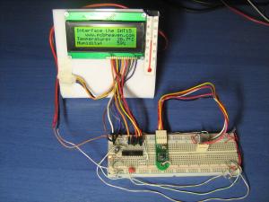
 The circuit mounted on a breadboard for testing The circuit mounted on a breadboard for testingThis could be my favorite sensor that i have interfaced to a PIC so far. There are actually two reasons for that. First, it is a single sensor that it can measure both temperature and relative air humidity with very high accuracy. But the basic reason that i choose this for my favorite sensor, is the challenge to get the measurement results.
The Challenge
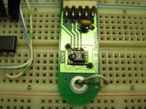
 The SHT15 sensor The SHT15 sensorAlthough it uses standard I2C protocol for the communication with the uController, the 12/14 bit return value needs yet many work to become a daily-understandable number. The temperature for example returns a 14-bit number. To convert this number into a oC, you need to apply the following formula:
Temperature = -40 + 0.01 x ValREAD
Of course using a pocket calculator, this is a 3-seconds calculation. But with the PIC, things are much tougher. The PIC can handle 8-bit numbers, that means numbers from 0 to 255. Moreover, within the instructions of the PIC there is no multiplication or division. That makes things even tougher.
But even more difficult is the humidity calculation. To get the results, you need to do many tricks. The calculation formula that needs to be applied to the 12-bit return value in order to get the humidity % is as follows:
Humidity% = -4 + 0.0405 x ValREAD + (-2.8 x 10⁻⁶) x ValREAD2
To solve the above two formulas, you need to have a couple of sophisticated subroutines prepared. Basically, you need to have a 16bit x 16bit multiplication routine, and an 24bit / 24bit division routine.
Calculate the temperature
This is by far the easiest part. Basically, what you need to do is to divide the 14-bit return value by 100. Then, you just subtract 40 from the result and that's all! If you have the appropriate 24-bit division routine it is very easy.
Calculate the humidity
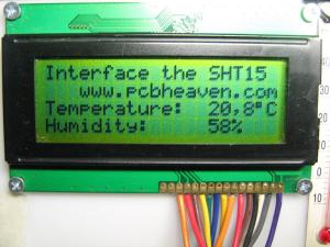
 A sample screenshot of the 20x4 LCD A sample screenshot of the 20x4 LCDHere we need a little bit more work. The procedure that i describe is not common and not the only one correct. Actually, there are lots of "correct" procedures and ways to solve the formula. The one i used is just one way that works.
First of all i calculate the ValREAD2, by multiplying the return value to its self. Then i divide this value by 1000. I multiply the result by 28, and divide the result by 10000. Look bellow:
P = ValREAD2 x ValREAD2
P = P / 1000
P = P x 28
P = P / 10000
What i've done so far is to have calculated the value for the 2.8 x 10⁻⁶ x ValREAD2. The first trick i did was to multiply the 2.8 by 10 and covert it to 28. To balance this, i changed the 10-6 into 10-7. Moreover, you can see that i chose to have 3 different calculations (P/1000, Px28 and P/10000) instead of 2 (P/10000000 and Px28). This is a very important step to maintain the accuracy. I chose the 1000 for the first division, because it is not too big to have a small number as a result (i do not use the decimals), and it is not too small, because the multiplication could overflow the 24-bit return word.
The above result is saved it for later use. Then i multiply the return value by 405, and divide it by 10000:
Q = ValREAD2 x 405
Q = Q / 10000
This calculation will calculate the other part of the formula: 0.0405 x ValREAD. There is not a special trick here, instead of that i multiply the 0.0405 by 10000 to convert it to 405, and after the multiplication with the read value, i divide it with 10000 again. I did not want to mess with decimal numbers.
Finally, all i had to do to get the humidity in percent, was to subtract the previous calculated value (P) from this value (Q), and subtract another 4 from the result:
Humidity% = P - Q - 4
I can say that i was quite aroused when the whole thing worked! And the fact that having decimal numbers in the humidity result is not necessary (not to say confusing), turns the above calculation series valid and accurate.
The Circuit
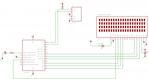
The schematic diagram is very simple. I use the PIC16F631. The microcontroller is the PIC 16F631. The communication with the SHT15 comes from pins RC6 (Data) and RC7 (Clock). The communication with the 20x4 display is done by using the short protocol (4-bit communication). The R/W wire of the LCD can be held permanently low (and save one I/O port of the PIC), as i only Write data to the LCD and do not Read any.

Notice that the Data bus of the SHt15 needs a pull-up resistor. An 1K resistor is enough. Higher values may cause problems as the rise and fall times will be higher. The LED is blinking every time a new measurement is taken.
Downloads
Here are all the files needed as well as the full assembly listing, to re-compile the program:
For those that do not want to recompile and wants it as-is, here is the compiled hex version to directly upload to the PIC:
Bill Of Materials
| Resistors |
| R1 | 100 Ohm variable resistor |
| R2 | 10 KOhm variable resistor |
| R3 | 330 Ohm 1/4Watt 5% resistor |
| R4 | 1 KOhm 1/4Watt 5% resistor |
| | | ICs |
| IC1 | PIC 16F631 Microcontroller |  |
| IC2 | SHT15 Humidity and Temperature Sensor |  |
| | | Misc |
| LCD1 | LCD 20x4 Character LCD w/ HD44780U1 controller |   |
| LED1 | LED 3mm red |  |
Relative pages
High accuracy temperature meterLow cost medium accuracy PIC temperature meterLearning PICs @ PCB Heaven On-Line BookLearn about the most popular PC Cooling methodsPeltier coolers (TEC) theory of operation
Comments
At 21 January 2015, 17:02:32 user Giorgos Lazaridis wrote: [reply @ Giorgos Lazaridis]@Raj Kumar I think it can be done, but you have to make sure that the protocols match. Check the datasheets
At 17 January 2015, 4:56:59 user Raj Kumar wrote: [reply @ Raj Kumar]Dear Sir.
Could I know whether i could use SHT 11 instead of sht 15 sensor for ur temperature controller.If so so what should I do/
Raj
At 31 October 2012, 7:28:59 user Giorgos Lazaridis wrote: [reply @ Giorgos Lazaridis]@mecs I'm sorry but i do not alter or make circuits on demand. Especially in old projects.
At 29 October 2012, 3:57:14 user mecs wrote: [reply @ mecs]@Giorgos Lazaridis
sir. i did try to simulate these in proteus but there was no display in the LCD. What could be the problem? I was hoping you could help me on this.. I intend to use this for my my little incubator so I could monitor the temp and the humidity. Would it be too much to ask if you can add a code that will trigger the relay on if the temp is 36.5 and also trigger the relay off if the temp is 37.5?
thanks and more power
At 20 December 2011, 6:33:29 user Kammenos wrote: [reply @ Kammenos]@Jason this circuit is only to demonstrate how can someone interface an SHT. A complete project requires much more coding for the PIC. The answer to your question is that you need to re-write the software for the PIC to do so.
At 19 December 2011, 17:22:29 user Jason wrote: [reply @ Jason]How can one set the temperature and humidity values for switching heaters / coolers etc ?
By the way, I love your website, I am enjoying watching the videos!!!
At 30 April 2011, 18:24:55 user Kammenos wrote: [reply @ Kammenos]@karla the board i used may be discontinued, i am not sure. I suppose that the board you sent me will work as well, as the sensor is the same. Regarding the capacitor, as i see, there is one SMD capacitor on the left side of the board as shown in the picture.
At 29 April 2011, 6:35:11 user karla wrote: [reply @ karla]http://www.sparkfun.com/products/8257 this is the web of the sensor that i found...
At 29 April 2011, 6:25:40 user karla wrote: [reply @ karla]so..i only have to follow the schematic? and...where did u buy the sensor..??cause u put like in a breakout board and i cant not find that kind of breakout. i found another that dont have the capacitor that is in yours,does it affect? do u have a special suggestion about this proyect?a detail?
i found this : https://02f9a18.netsolstores.com/cart.aspx
thanks for answering.
At 29 April 2011, 5:20:22 user Kammenos wrote: [reply @ Kammenos]@karla whenever there is a capacitor in a photo that does not exist in the schematic, this is a smoothing capacitor for the power supply. The are connected in parallel to the supply voltage. The electrolytic capacitors are always 1uF and the ceramic (or other) is 0.1uF. It is up to you to decide if you will use a capacitor or not, and how many you will put. Depends on your supply voltage quality.
At 29 April 2011, 5:00:07 user karla wrote: [reply @ karla]hi!
i would like to ask u where do u connect those capacitors and what value do they have cause in the schematic it doesnt come..i will apreciate if u answer me soon..xD
At 29 March 2011, 17:14:54 user Kammenos wrote: [reply @ Kammenos]@volk the one described in the datasheet in the bill of materials of this page. the brand is irrelevant, the controller and the pinout is what matters actually.
At 29 March 2011, 16:40:01 user volk wrote: [reply @ volk]What LCD module used in this meter? The Bolymin? The Winstar? Type etc. ...
At 29 March 2011, 14:30:55 user Kammenos wrote: [reply @ Kammenos]@volk i'm not sure i have not check it
At 29 March 2011, 14:20:24 user volk wrote: [reply @ volk]Hi!
Will be work this meter KS0066 or equivalent built-in controller and 20x2 character?
Thanks
At 27 March 2011, 9:19:31 user Ahmed Taha wrote: [reply @ Ahmed Taha]Dear Giorgos Lazaridis Sir;
I tried to simulate that circuit in Proteus program with that code but it did't work
can you help pls?
At 23 March 2011, 9:45:31 user Asif Rizwan wrote: [reply @ Asif Rizwan]THENX FOR CIRCUIT I WILL TRY CONVERT YOUR ASSEMBLY CODE TO C LANG.
At 2 January 2011, 8:13:59 user Kammenos wrote: [reply @ Kammenos]i made these myself. there is an excellent document here:
http://www.sparkfun.com/tutorials/110
Eagle library is the most difficult to use. I do not know why they did it that stiff. It is such a nice piece of software, and yet copying library footprints is a job for pros. But you can make new parts from a scratch quite easily. In my plans is to publish a PCB Heaven eagle lib with all the parts that i have used over time.
At 1 January 2011, 20:44:43 user herctrap wrote: [reply @ herctrap]where did you found that 20x4 for eagle?
thanks a lot
At 3 November 2010, 3:49:54 user Muhammad Anowar Kabir wrote: [reply @ Muhammad Anowar Kabir]Dear Giorgos Lazaridis Sir,
Your PIC Precision Thermometer and Humidity meter using the SHT15 , is very nice.Please include it, Set temp. option ,so that it can be use as a temperature controller for Egg incubator,and it can control Heater and Fan. I am waiting for your more Projects.
Please mail me.
Muhammad Anowar Kabir
makabir2010@gmail.com
At 24 September 2010, 18:07:27 user stijn wrote: [reply @ stijn]Hi,
thank you for answering my question.
if anyone can write it in the C language that will be very thanksfull
(my english is not so good) but I will serach the internet and I think that will laso certainly help.
Thanks anyway
At 21 September 2010, 17:20:49 user Kammenos wrote: [reply @ Kammenos]stijn, my assembly is quite good, but my C kinda sucks. I am sorry. If someone else can write this to C, i will post it with pleasure.
At 21 September 2010, 16:50:40 user stijn wrote: [reply @ stijn]Hi,
this is a request.
Can you write the program in the C language? please
Thank you
At 31 December 2009, 14:20:31 user Javier Puiggros wrote: [reply @ Javier Puiggros]Hi Great work with SHT sensor.
We are working for 3 years with SHT15 so far, and some problems with dust. It looks like you are using a board with filtercap option, where did you get it? |
|
 HOT in heaven! HOT in heaven!

|
|

 Home
Home
 Projects
 Experiments
 Circuits
 Theory
 BLOG
BLOG
 PIC Tutorials
 Time for Science

 Contact
 Forum
Forum
 Projects
 Experiments
 Circuits
 Theory
 BLOG
BLOG
 PIC Tutorials
 Time for Science
 RSS
RSS