Shortly after i published my IR Short Distance Beam Cut Detector circuit, i began receiving emails and comments, asking how to increase the range. As a matter of fact, that circuit was designed for a very specific application: it had to be precise and sensitive enough, because i wanted to use it for the straw separator of my coffee maker machine. Because people keep asking me for a long-range IR beam break detector, i made this circuit which has a range of nearly 10 meters (33 feet), with only a single high power LED, using no lenses.
The Circuit - The Transmitter
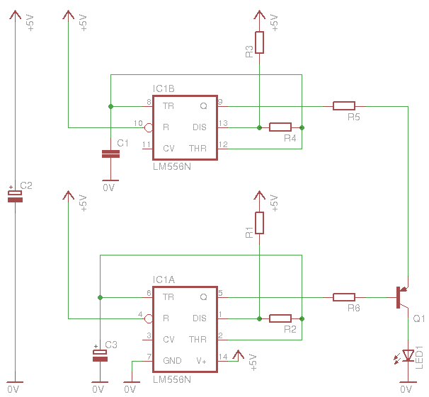
Here is how the transmitter works. As you see, i have use one 556 timer, which contains 2x555 timers. You can use a 556 as well, or you can choose to use 2 individual 555 timers check the 555 timer theory). It will operate without any problems. The first part of the 556 (IC1A), generates pulses of about 1.5 msec duration, with 30 mSec interval (signal frequency is about 32 Hz). The second part, generates the carrier signal which is 38 KHz. The transistor Q1 switches the carrier signal (38 KHz) on and off, according to the previous (32Hz) signal. In simple words, the IR LED receiver a pulse train of 38 KHz, 32 times per second (32 Hz), each time for 1.5mSec. This is the modulated signal. To further understand this circuit, i got some screenshots from the oscilloscope (as always, click to enlarge images):
This is the 38KHz carrier signal - the correct frequency for my IR receiver
These are the modulation pulses (32Hz) - will be inverted after the transistor
Each pulse has 1.5 to 1.6 mSec duration.
These two signal are then modulated (and inverted) with the transistor Q1, and here is what arrives at the IR LED:
These are the inverted and modulated pulses. On every positive duration of the pulse, the carrier wave (38KHz) is transmitted
This is only one pulse on the screen of the oscilloscope (zoomed). The 38 KHz signal can now be seen clearly
So, the IR transmits 38KHz signal, with 1.5 to 1.6 mSec duration and 30mSec interval. This is what the receiver must receive.
Bill Of Materials - Transmitter
Resistors
R1
Resistor 47 KOhm 1/4 Watt 5% Carbon Film
R2
Resistor 2.2 KOhm 1/4 Watt 5% Carbon Film
R3
Resistor 6.8 KOhm 1/4 Watt 5% Carbon Film
R4
Resistor 22 KOhm 1/4 Watt 5% Carbon Film
R5
Resistor 220 Ohm 1/4 Watt 5% Carbon Film
R6
Resistor 1 KOhm 1/4 Watt 5% Carbon Film
Capacitors
C1
Ceramic Capacitor 680 pF 50 Volts
C2-3
Electrolytic Capacitor 1 uF 50 Volts
Transistors
T1
2N2907 General purpose amplifier and switching transistor
Semiconductors
LED1
High output IR LED
Integrated Circuits
IC1
556 Dual 555 Timer
What is this "High output IR LED"
I tried several cheap IR LEDs - No good
I mention this IR LED as high output, but i do not give any part value. Frankly speaking, i do not know one. I tried several LEDs that i got from different suppliers -including ebay-. One word: Do NOT shop this from ebay! No matter what the seller says, just, don't. All the LEDs i tried had a range of 2(ebay) to 4(others) meters. So, i did some more research and i found that there are actually "high output IR LEDs" such as the 510E850C from Hebei I.T. (Shanghai). Although i have not tried this LED, i suppose that this is one good IR LED for remote controls, or maybe it can be TOO MUCH (100 mWatts !!!!!!). In any case, if someone tests or knows another IR LED suitable for remote controls, then please let me know.
What i did for my remote? Well, it just happened to have an old remote control in my museum. I hacked it and removed the IR LED from inside. Luckily, it did work perfectly. With this LED, i managed to get 10 meters range (or maybe more)! What you need to have in mind, is that, unlike normal LEDs, these LEDs have usually a low forward voltage drop. My LED required 1.5 volts (that's why i chose a 220 Ohms resistor). In case you select a different LED, be sure you change the R5 accordingly.
At 13 January 2016, 21:09:09 user Phil wrote: [reply @ Phil]
Hello Giorgos, and firstly thank you very much for sharing this circuit.
I built it and it works a treat. I have a range of about 5m indoors and not yet tested it outdoors. The IR led I used was "Night Vision 5mm 180mW 12 degree 875nM IR LED's Qty 10 New Vishay TSHA5202" from eBay item number:121675391460.
This seems to be quite a powerful led so I would be interested to know how it would be possible to increase the power to this led in the cct.
The output waveform at the led shows a 1.52V peak to peak, and a rms value (calculated by the scope) of 355mV.
The ideal DC voltage for this led seems to be 1.2V, do you think we could push the RMS value up to closer to 1.2V, say perhaps 1V ?
Anyway good fun, and I shall do some more testing over the next few days.
Thanks
Phil
At 16 December 2015, 16:04:11 user Mobi wrote: [reply @ Mobi]
Hello, I am aiming to make an IR transmitter for a range of 3-4 meters, can you plz help me out?
I have a barn with an older automatic door opener that doesn't have a "Safety eye" for stopping/reversing the door when it is closing. If I could wire this output into the stop or reverse button (which is just a contact closure), would that work?
Would you be able/willing to build this for me? Contact me off-list for discussion/negotiation.
Thanks
First of thanks for sharing. This is indeed a great help for beginner like me to understand real world application based on the 555 IC.
From what I know, the 555 osc freq formula should be 1 / { C * ln(2) * ( R1 2*R2 ) }.
But, using this formula with your Resistor and Capacitor value yield 28kHz(ICA) and 41kHz(ICB) instead of 38kHz and 38Hz.
Could you enlighten me on what formula did you use to calculated your astable oscillation frequency?
@GRAHAM Click on the diagram to see in full size ;)
At 15 October 2014, 16:20:01 user GRAHAM wrote: [reply @ GRAHAM]
Hello, I was interested in building your long range infra red detector, but I am finding the circuit diagram of the receiver difficult to see, it is not very clear. I would be most grateful if you would E mail me a copy.
At 23 September 2014, 22:09:53 user gabriel wrote: [reply @ gabriel]
Can i use this design to have say 10 transmitter and 10 receiver (triggers light from any transmitter?
Light will be switched ON till transmitter is switched OFF?
At 10 September 2014, 22:28:51 user Owen wrote: [reply @ Owen]
How would you design the receiver circuit for an long range ir distance measurer, using the TSOP183 chip. Also connecting it to an ADC of an microprocessor.
At 13 May 2014, 17:59:45 user ali wrote: [reply @ ali]
hello , i perform the cct but the output ir from led is very poor why?
i delete the resistor 220 ohm . but the receiver do not work true and do not receive from the transmitter kit ?
HI thanks for good project
after i build this , its work well around 8-9 meters , and beam of IR TX is sharp and strange not like TV remote as can reflect and bounce with wall or proof
I test try used SONY TV remote is can control RX this project too
and
when i point TX to Television and try SONY remote to control its have effect difficult to control the TV
so
I think this project have effect with TV and Remote TV, not suitable use near TV.
or you have good advise for this problem
Hi Giorgos, i dont know much about IR but is it possible to have a single beam broken at various positions along the beam and the time and position/ location of the break.
hello sir, i am making my final year project on wireless solar power transmission. i am using TSOP1556 as an IR reciever. can i use a LED from remote as an IR transmitter to get a range of 10m or more???
Hellow Sir,
on behalf of my recent post i got ir receiver(tsop-1738).Can i use this one instead of tsop-1838?Please reply me as soon as possible because i can't proceed on without resolving this issue.(Reply me on mumtaz.naich@gmail.com)
Thanks
Hellow Sir I am doing my final year project on motion detection based sequirty system and trying to design ir transmitter and receiver but the problem is that here TSOP1838 and even no other receiver of tsop series not available so what i do and what type of ir receiver i use instead of tsop-1838.Plz reply me on this email(mm_0454@yahoo.com)
Thanks
@Abhishek No it does not help the range at all. It helps the filtering procedure (which can be distinguished from ambient noise) and also its good to transmit more data in less time.
@Felix Khan Hi Sir,
I am doing my final year Engineering. I am doing a project to sense a thin wire or a thread that falls in the path of the IR beam. From your comment, i understand that your circuit will solve my purpose.
It would be really very helpful if you can send me the circuit and its related details. My mail id is pradipma@gmail.com
Thanks and Regards,
Pradeep
Hey. I am trying to use IR1838 with the IR transmitter. But unfortunately, when i try to place IR led in front of the receiver, there is no chgange on the pin 1 of the IR 1838. But when i use the AC remote for random checking, i get a momentary zero pulse(~2.1 V). So where can i possibly wrong. The IR transmitter is just an ordinary transmitter purchased from the market. And i have generated(~37.3Khz) carrier from the micro.
Hoping to hear from you soon.
At 21 September 2013, 14:16:20 user Pete wrote: [reply @ Pete]
Can you do a gauge rpm meter (with lcd 2x16) on HV cables, to gasoline engine? i searching for it... i wanna to do it alone... thanks a lot!
@imran I just explained how to calculate speed from known distance. Reverse to get the time. As for the design, i'm sorry i do not design circuits on demand.
At 15 September 2013, 10:46:05 user imran wrote: [reply @ imran]
sir actually i want to know how to calculate time which an object takes between two IR sensors having a known distance.so what timer or IC i should use in my project.how to inerface that IC with IR.I want to use this for calculating a speed of a car on the road.plz reply at imran_manzoor16aug@yahoo.com
@Imran Speed = meter per second (for example). So separate the two sensors by say one meter. Then have a digital counter counting 100s of miliseconds (that's 100msec per count or 10 counts per second). When the object passes through first IR beam, the counter starts, then through the second it stops. The count that you see is how many 100s of miliseconds it took for the object to travel one meter. Say you see 1500mSec (thats 1.5 seconds).
1500 msec = 1 meter
1000 msec = x
----------------------
x = 1 meter x 1000/1500 = 1 x 0.66 = 0.66 meters/sec
Of kmph:
1500 msec = 0.001 km
3600000 msec = x
----------------------
x = 0.001 x 3600000 / 1500 = 2.4 Km/hour
At 15 September 2013, 10:16:35 user Imran wrote: [reply @ Imran]
that work was fantastic!!!!!
sir i want to use two infrared sensors.the distance between them is determined and known i want to calculate the time that an object takes to cover that distance.what should i do...how should i proceed...any one can help me please....
my address id (imran_manzoor16aug@yahoo.com)
waiting 4 reply...
great circuit. will be building this shortly if it does what I hope.
what sort of angle will the transmitter output through.. as in if I had one transmitter on a flat aurface such as a wall but needed to detect an object within a 45degree arc from the transmitter and used multiple receivers.. that way I could detect at what angle the object is at from the wall.
could I then use another transmitter on an opposite wall with multiple receivers on the other side (basically 180degrees to each other) I could then uae it as a basic position calculator by comparing which beams are broken..
@Rudie Lamprecht You can increase the distance with more powerful LED transmitter indeed. As for the laser, it will not work with this circuit. Commercial mW lasers are quite safe for humans and animals as long as you do not look directly the beam
Thanks for your good design. Will it be possible to go to say 30 m ? Will I need lenses or do I need to amplify the signal otherwise ?
I have seen the 'expensive' IR beam detectors used for home security systems, that go up to 50 m but they are too expensive e.g. ~ US $ 70.
What do you think about laser for a similar application such as the 'toy' laser pointers sold cheaply on EBay ? If I use laser can I make it safe (e.g. filter) so that it is not harmful to human or animal?
dear sir
isaw your model long range
here i need this idea for usuing to not forget the child in the it happeed here 3 times
if this circit can remaid the driver that maybe you forgot the child can save life
is it possible to put a stop alarm in
the remote and reniew when it has contact again in the car
i need for car rescue
thank you sir david
The following links will be available for 30 days(freepdfhosting site restriction).
It is a PCB layout for the transmitter using surface mount parts.
PCB mask: http://freepdfhosting.com/05dab4958c.pdf
Silk Screen: http://freepdfhosting.com/f06c4596ec.pdf
I have tried to mark all the components on the layout to make assembly easy. It fits into the "ABS Box - 34 x 16 x 24mm" on bitsbox.co.uk.
Note that I have not tested the endurance of the TSAL6400 IRLEDs, but they should last well as they are intended for remote controls and matches the TSOP2438 perfectly.
At 2 July 2013, 1:40:40 user Ong wrote: [reply @ Ong]
Hi I would like to know, because some of the component he used has already discontinued, is there an difference with
2N2907 with 2N2907A
CD4017BE with the one he's using
BC548B
@Sir N Most (if not all) ebay LEDs are plain crap. Rubbish. I can tell because i ran some tests for a project that had to be reliable and cheap. The test was simple: I had 4 LEDs at 5,10,20 and 25mA for 2 weeks. I will re-run this project and post the results in the site BLOG. In short, the overpowered 25mA LED died within a day (that is normal), the 20mA LED died within a few days, and the other underpowered LEDs turned dimmer day by day (compared to new LEDs that i had).
In other words, you pay for peanuts, you get monkeys...
Don't blame it on the eBay suppliers that IR-LEDs with a wavelength of ~830..850nm is not working aces with a receiver that needs a peak wavelength of around 950nm!
The former is used for eg. night vision cams (among others), while the latter is used for remote control. Just get an LED with a wavelength matchibg your receiver (should be in the datasheet) and you're green, whether you get it from eBay or elsewhere.
Tell me if you want some design/evaluation help with both your IR-gates :)
I found something interesting on the timings for the 38KHz pulses. At 31ms/3ms, it is possble to avoid detection if you run past the beam. By changing the transmitter to transmit the 38KHz pulses at 10ms/1ms, which is still within the specs of the TSOP2438(it might not be for some of the other TSOPs), I avoided this problem. This requires the 47K to be replaced by a 15K and the 2k2 replaced by a 1K5. I did not calculate the values for the receiver as I don't use it, I use a 12F675 microcontroller, so I just adjusted the values in the code.
I thought it might be of interest to some.
@JunTung There is no opamp in this circuit. Only one relay. Connect the 5v to the relay, then the negative of the buzzer through one open contact of the relay to the ground.
In the UK the 2N2907 is expensive( > £1 at Farnell). A cheaper alternative is the BC557 at 12pence from bitsbox.co.uk. They also sell the TSOP2438(instead of TSOP1838) and TSAL6400(IRLED) and resistors and caps cheap). The only part I could not source from bitsbox was the decade counter(4017), so I left off the NE555 and 4017 on the receiver and used a PIC12F675 instead and programmed it. That negated the best part of the receiver circuit, but made for an interesting little project. I have a PCB layout for the transmitter, but dont know how to upload it. It is done with ExpressPCB
(http://www.expresspcb.com/expresspcbhtm/download.htm).
@Giorgos Lazaridis
Sir, if relay can replace the op-amp, can you show me how to connect the relay together with the buzzer ? schematic K symbol means the relay right?Thanks and much appreciated :)
@Giorgos Lazaridis
Sir,is this possible to replace the led to buzzer? i mean when the beam is cut then the buzz will produce sound?according to the output voltage.Let said if it is too low,can i use a op-amp to make d voltage higher?or any suggestion sir?
@JunTung C1 is the supply voltage smoothing capacitor. IC2 counts the pulses from the 555 timer. The IR pulses reset this chip. If the IR beam is cut, there is no reset signal and therefore the IC2 counts up to 10 which enables the output.
Hi sir, i follow all your stated component except for IR LED n receiver. In transmitter part my IR LED cannot work becoz i get a very low voltage using DMM to check it. Is the IR LED problem? normally how much voltage cause the IR LED light up?
Sorry I missed this in my previous posts:
This is a great and clever circuit that is quite low-cost and easy to make.
I especially like the receiver part as it is innovative use of simple components without the need for programming a micro-controller.
@Gerhard Smith No you are not missing something, this is correct. I used this at 10 meters and works with as low as 20mA - I do not have any reference of this LED (max current, peak current, frequency etc), and since it works at 10 meters, its fine for me. To drive more current, you need an extra transistor (as you mentioned)
@Ammar:
The TSOP1156 requires a 56KHz carrier so you can try the following values on the transmitter(no change to receiver except the TSOP):
C1 = 0.0001uF
R3 = 18K
R4 = 120K
Look here for the NE555 frequency calculator:
http://houseofjeff.com/555-timer-oscillator-frequency-calculator/
Hope it helps
Note in a funny way this might be better as it will interfere less with the 'normal' remote controls at 38KHz.
Am I missing something here:
If the transmitter supply is 5V then the current through the IRLED will be limited to 22ma(5V over 220R ignoring the IRLED resistance) - this hardly turns the IRLED on(100mW max). The reason for the 38KHz and bursts used in IR transmissions is to turn the IRLED on hard (200ma=max for TSAL6200 IRLED) for short bursts, allowing it to cool in between during the off period for the 38KHz and the bursts. This way much longer ranges can be achieved.
However, the 38KHz 555 pin3 cannot supply 200ma, so the circuit would need another transistor, with emitter connector 5V supply, (similar to tranny on second 555) to provide the current to Q1.
So:
By reducing R5 from 220R to 33R and adding the transistor, the current through the IRLED would go to 150ma and the wattage to 750mW, which should give a much longer range.
hi sir,just want to ask you about the circuit diagram. What is the function of C1 and IC2p there? and also the receiver ic, is it the Vs is the Vcc for this ic and Vo is the received signal output? This is nice circuit. Thanks and much appreciated sir! :)
what if TSOP1828 isn't available i tried to get it from all my sources.
at end i just got tsop1156 what i have to change in circuit accordingly to use tsop1156
plz explain how u decided the burst length equal to 30ms and silence to be 1.5ms while designing this circuit.....What effect can this burst length has on the range and proper detection of IR rays.....plz explain...
can u please explain the calculations of resistances and capacitances as mentioned regarding the 'On' time and 'Off' time of the timer for both the cases i.e. 32hz and 38khz....
Yeah, but i used ksm80 sensor which is similar to Tsop and used 38k hz in the transmitter but i got no progress :(
So i thought the difference in that i send continuous oscillations and you send pulses..
@samar mohammed @samar mohammed @samar mohammed
reviver circuit doesn't work we don't know what is the problem we test transmit circuit we don't get exactly 38 khz so we use choose variable resistor instead of this R4 & R5 to get the specific hz finally we get it our problem was with receiver circuit no changes happen to it even the circuit with 1cm distance could u just explain 4 us the main idea for it
and we want to know how can i know that transmitter circuit will work for 10m
thanx a lot ^_^
hello sir
i try to do this circuit but it doesn't work... cause i don't find 1838 sensor in my country i use 0038 instead of it is that OK or will damage work ??
thanx ^_^
Hi, first of all, congratulations for the excellent work in this circuit. I want to use it to count the number of people inside a particular room. My idea is to use two transmitters and two receivers, side by side, far from it other aprox. 10cm. So ,depending on which one is interrupted first I can tell if there is a person coming in or out. Can use each circuit in a different frequency so one don't interfere in the other one signal?
hi friends...i am using this circuit for vehicle type and speed detection.....can anybody tell me how to connect the output of receiver to microcontroller 8051....thanks in advance
@Anibal Actually you do not need any change. Just use the other contact of the relay;)
If you badly want to change the operation, then you will have to add an inverting transistor between the 4017 and the T2 driver.
@jason of course you can eliminate both chips if you use one microcontroller. I've never used microC
At 10 October 2012, 1:56:18 user jason wrote: [reply @ jason]
i.m planning to use this on my car parking counter using pic16f877a,do you think i can ignore the ne555d and the 4017 on the receiver section and connect the output of the tsop1838 on the microcontroller? do you know how can i programmed it usiing mikroC?
Plz show me the connections to CD4017CN cmos counter and what about the specific frequency from 555 to the clk input to counter...plz provide me with the connection diagram
I just make a circuit for IR cut-beam circuit consist of AX-1838 IR receiver module plus the designed circuit for IR short distance cut-beam ...Please i want to publish the design for all people and send it you specially for the person who design the above circuit.
I have a clip that shows the circuit operation plus the circuit design.
@Giorgos Lazaridis
another question: does%uFEFF the transmitter work if i connect e.g. 20 IR LEDs parallel to the one on the output, i.e., would all 20 LEDs transmit modulated 38kHz signal as powerful as this one?
@Islam Qabel i do not understand the question really. Please sign up to the forum and upload the schematic. The conversation in the forum will be easier.
Thanks a lot for your reply. But i think you are not recognizing my design well. If you want to send the schematic ok. I am using AX-1838 IR receiver module and sending 1 Khz and 38 KHZ carrier frequency. I intended to use micro-controller to decide IR cut-beam or no IR cut-beam. Micro-controller receives the output directly from receiver module ....the output is 1 KHZ . The micro-controller decide beam-cut or not as following:
Mico-controller counts the input pulses from the output of IR module (It should be 1000 or 1KHz). when No-beam cut , the counter is around 1000 pulses .. decide no beam cut .when beam-cut, counter is zero decide beam-cut. The disadvantage in this method that it take small delay when deciding.
@manac it is not exactly a gap, it is the pulses of the signal. I do not recommend you use something unmodulated since there are many sorts of IR sources that will cause parasites to the system, like the sun and most lamps.
@Giorgos Lazaridis As I have understood from TSOP1738's datasheet it also requires a small gap.. Could you recomend me a detector that doesn't require that? I only need a range of 2 meters max, as I plan to put it on a stairway (on each stair)...
@manac The difference between TSOP1738 and TSOP1838 is that the TSOP1838 requires a small transmission gap between data sent, approximately 20mSec. If you continuously send a signal to the TSOP1838, it will eventually reject it. It is more suitable for remote-control applications rather than IR beam cut sensors. That is why i have the signal gaps in the transmission.
Check page 3 of the datasheet that i provide for the TSOP1838 (Suitable Data Format).
So, for this application, you can replace the TSOP18xx series with a TSOP17xx series
@Giorgos Lazaridis thank you... another question: does the TSOP 1838 produce a continuos signal on its output or the output signal is at 32Hz? And is ti replaceable with TSOP 1738, is there any difference between these two parts except for the output logic state (TSOP 1738 produces LOW state when 38 kHz is provided)?
@Darrel This is what it should do. The remote control sends pulses with very longer intervals, something that the receiver does not accept as a serial signal, therefore it appears to give pulses.
@Giorgos Lazaridis ok so the closest thing I had was 3 100ohm resistor in parallel to give me 33ohms. now the odd thing is when ever i break the beam the reciever picks it up but when i use the remote i get pulses as i hold the button. Isnt the transmitter supposed to do the same or is it now working properly? Just so you know im using leds on the reciever npn transistors(T1) to pick up the pulses.
@Darrel It is not a "bad IR", it is just not correctly rated to fit my circuit. You need to calculate the R5 for your LED. So, you power the circuit with 5 volts, and you want to provide 1.3 volts to your LED at which it draws 100mA. This means that you need the resistor to drop 5-1.3=3.7 volts at 100mA
R5 = U/I = 3.7 / 0.1 = 37 Ohms
The resistor that i use is probably too big for you. You can also connect 2 LEDs in series and achieve 1.3*2 = 2.6 volts, and then only 5-2.6=2.4V must be dropped on R5:
R5 = U/I = 2.4/0.1 = 24 Ohms
Similarly, for 3 LEDs in series, 5-3x1.3 = 1.1;
R5 = 1.1/0.1 = 11 Ohms
Choose which setup you like and use the best resistor.
@Giorgos Lazaridis the IR I used has a forward voltage of ~1.28V and rated at 100mA. Im fairly new to electronics so can you tell me why this might be a bad IR to use and possably a way to make it work?
@Darrel do not expect to see any sort of blinking, it is too fast for the eye to see. Probably your IR LED is dead (since the normal LED lights). Make sure that the IR rating is correct (voltage/current) because i do not use high current IR transmitters which operate at a voltage nearly the same as normal LEDs. If you use IR LEDs with forward voltage 1.3 volts, it will have a very short and miserable life on the board
My reciever works which I tested with a remote, but my Transmitter isnt powering the IR which is shown by my reciever not being able to pick it up. I did the phone camera already and the IR light did not show up on either the remote or my circuit. Also when I replaced the IR with an led the led worked but it wasnt blinking so I dont even think the circuit is oscilating. So what should I check?
Hello I recently built the transmitter and receiver and im having a problem with current to my IR. the receiver works well I was able to test it with a remote but my transmitter Isnt powering the led. im using a 5v usb supply and I believe the circuit is wired right. I dont have an osiliscope but I have been taking measurement with a multimeter.
also i switched this IR and its resistor out for a red led and a resistor and it lights up. Do you know why the IR doesnt light up or getting the current it needs?
@Tanay At maximum 555 frequency, the obstacle has to remain for one full IR pulse plus 1/9 of it. That is 31 mSec 3.4 = about 35 mSec. After 35 mSec, the load will be activated.
Good day sir.
My name is Saiful, from malaysia.
My email is nnytime_2cu@yahoo.com.
tq so much for giving me the chance to use your circuits :)
I have questions regarding to your Long range IR beam break detector circuit.
I'm using your circuit as my project for my Final year project.
I have a little problem with the transmitter.
I'm using a regular IR LED.
When it transmit, the receiver starts to blinking.
But when i used a tv remote control, it was working well, i mean OFF lights completely when i press any buttons from my tv remote control.
What was the problem sir?
Do i need to change the IR LED transmitter into something better sir?
another question about the receiver.
how can i invert the indicator which means, when i transmit, it goes ON.
any alternative, sir?
Looking forward for your answer.
Many of the people who have tried making this circuit would have found it fall short of 10 meter distance.
I do have a circuit I designed back in 1992 that using a Power Supply PWM. It works great with old Radio Shack GP1U52X IR receiver. It allows you to adjust the sensitivity to sense even a very thin wire. The IR LED I used were SHF485 designed for 200mw and a surge current of 2.5A. It is a rugged and designed for high power IR applications.
If any of you are interested in my IR break beam circuit then please send me an e-mail and I will be happy to send you an updated version of my circuit.
My IR transmitter and receiver is designed to fire a camera or a photoflash. However, with a little modification one can use it for all sorts of application.
This IR transmitter can be use with just about any receiver since you are able to adjust both the Pulse Width and the Modulation Frequency.
@ERWIN I'm happy that this works for you. As for the donation, i have a donation button in the home page, but i really prefer receiving things instead, like books (used or new), tools (again used or new), broken devices, old motors, lcds, unused chips, you know, things that can be used for the site and can be easily shipped. Money have no "memory", so if i add a book to my bookcase which i received from a person from a far country, that would be amazing.
At 11 April 2012, 21:54:40 user ERWIN wrote: [reply @ ERWIN]
i;ve got the reciever on page 2 , thanks !How about a donation on this site, do you accept it?for the benefit also of those newbies and electronics enthusiasts and to keep it running,,,,what can you say gentlemen?
At 11 April 2012, 21:46:34 user ERWIN wrote: [reply @ ERWIN]
Question again, are we gonna utilize the reciever circuit of short distance project ?what reciever are we gonna use on this one?thanks!
At 11 April 2012, 14:14:11 user ERWIN wrote: [reply @ ERWIN]
Thanks for publishing your circuit online , I will build this circuit
since one of my belonging was stolen inside my property, so plan to install this in the perimeter of my property and planning to install
cameras now.Thanks again and more power.
@ADEL here is how to do it. The emitter of T2 must be connected directly to ground (remove the relay completely). Then add a resistor at the collector of the T2: One side of the resistor goes to 5V, the other goes to the collector of T2. The microcontroller will then be connected at the point where the resistor connects to the T2 collector. The resistor should be something like 2200 Ohms or similar.
At 14 March 2012, 14:31:06 user ADEL wrote: [reply @ ADEL]
thanks for your efforts
can i connect the ouput of reciever circuit after the R7 to the input of micro controller to count the number of blocking and if it need any additional commpenets i hope you give me your experince
@Kevin the point is that the tsop has an internal transistor which reverses the signal. what you say is correct, but the difference is that the tsop has high voltage in standby and sinks when ir is received.
Hello, and thank you for this helpful article! I am an electronics amateur, so I apologize if this is a basic question. I am trying to build a beam break circuit to trigger events in a behavioral neuroscience experiment. Before building I tried to simulate the circuit to see if it behaves the way I want, but got strange results.
It seems to me that the voltage at the reset pin of the counter is low during positive pulses from the TSOP module, and high during the spaces between positive pulses. This results in the alarm being triggered only when the IR beam is detected as being 'on' for too long of a time. I found that replacing T1 with a PNP transistor allowed for the appropriate behavior. It seems that in your design, the pulses shunt the current going to the reset counter to ground, allowing for the counter to advance to 9. Am I correct in thinking this, or am I missing something?
@ADEL a pull-up resistor is connected between the positive supply and the pin you want to "pull up"
At 29 February 2012, 6:44:43 user ADEL wrote: [reply @ ADEL]
I THANK YOU FOR THIS CIRCUIT VERY MUCH, I ASK ABOUT THE PULL DOWN RESISTOR WHERE I CONNECT ON THE PINS OF THE MICROCONTROLLER WHEN I USED THE CIRCUIT AS VISITOR COUNTER
I HOPE YOU ANSWER ME AS SOON AS POSSIBLE
THANK YOU VERY MUCH
@specticals hello! first, this is not laser, it is infra red. As for your question, in a single word: yes, you can connect it. But you may face problems with bouncing so some kind of one-shot circuitry would be good to have in between.
I am just wondering if it would be possible to have 2 of these circuits, 1 connected to the up input of a (74LS193) and the 2nd connected to the down input so that when the laser has been crossed at the up input it will count up one on the 7 segment display and then down 1 if the 2nd beam is crossed.
@Specticals you can do this. remove everything after R7 of the receiver, and connect the R7 to the clock input of a BCD counter (eg: CD4518). Then use a BCD to 7-seg decoder (eg cd4511) to drive your 7-segment
Hello,
can anyone tell me if you are able to connect a 14 segment display onto this and have it count up/down from 10.
what components and modification may be needed?
@Ravi you cannot measure it with volt-meter because of the frequency. You can only put an oscilloscope to test. As for the voltage, this is not standard. If you scavaged an LED from remote control, then you probably need about 1 volt across the LED. Any more than this may harm it. Usually, IR LEDs have 1.2 forward voltage, but i used one with 3 (different LED).
You can make a test to see the maximum voltage across the LED. Connect R5 to the positive and R6 to the negative supply. This will light up the LED at full brightness. Then you can measure the voltage drop across it with volt-meter. But if you have done something wrong with R5, the LED will burn instantly. I suggest that you start with a bigger R5 value and do this test until you get the desired voltage.
At 6 February 2012, 19:28:38 user Ravi wrote: [reply @ Ravi]
@Giorgos Lazaridis
sir what is the required value of voltage across the ir transmitter ?
i got just 0.13v
@Ravi i am not sure for the differences between the tsop17xx and 18xx, but from a quick look i saw that 18xx has more "tight" filters. Normally, the 17xx should work. Make sure that the transmitter works correctly. An oscilloscope would help. Unfortunately i cannot do much without more data.
At 5 February 2012, 19:08:59 user Ravi wrote: [reply @ Ravi]
@Giorgos Lazaridis
thank you very much for that
i have done everything whatever is shown, but i have tsop1738.
so can you please tell me what are the changes i should have.
i have use ir led of a TV remote,and its working but receiver circuit is not work..
At 1 February 2012, 19:18:04 user Ravi wrote: [reply @ Ravi]
hello
please anybody tell me that is there any problem regarding to common ground ? I've used only 1 source of a power supply for both transmitter and receiver.
At 18 January 2012, 19:00:07 user Daniel wrote: [reply @ Daniel]
its just that am doing a project and this circuit has almost everything i need for it but for my circuit i need an output pf 1 pulse per millisecond. but thanks anyway
@Daniel i really do not remember the formula for calculation and this is an old project. But why change the time?
At 18 January 2012, 15:03:21 user Daniel wrote: [reply @ Daniel]
on the transmitter circuit, what value for C3 and R2, do you think i need to in order to archieve an output of 1 millisecond resolution. thats to generate 1 pulse every millisecond.
thanks
@Patel yes it will, i made this circuit for microcontroller interface. Remove T2 and K1, reduce R7 to 1KOhm and connect it to your microcontroller. You may need to add a pull-down resistor like 10K.
At 12 January 2012, 8:44:51 user Patel wrote: [reply @ Patel]
Sir,I want to connect microcontroller ... it will work properly??
@j.j.sathian here is a link with excellent high-power LEDs:
http://alan-parekh.vstore.ca/index.php/cName/leds-special-leds/osCsid/caeb2e24905d97d8d46df57e08cfa4df
@sam what kind of problems do you have in the forum? And what timer ship???
At 30 November 2011, 21:07:20 user sam wrote: [reply @ sam]
I'm having difficulty logging it into forum.
I'll post a close image as soon as I could log in...
I'm also wondering about the rest pin in the timer ship. Is it inverted?
@servesh with what do you measure the voltage and the frequency? are these peak to peak values from oscilloscope? the voltage across the led must be according to the manufacturer. Usually, IR leds may have about 1.2 volts (to work on remote controls)
hello sir;
sir i hv made this ckt .and i hv used led in the out put of receiver ckt as indicator . this ckt is good when d distance b/w tran. and rec is abut 1.5 meter and led is high (glowing), but when i increase above 2 meter led on receiver ckt start blinking
After giving a lot of time i found following results-
1- The receiver circuit working well with TV Remote up to 10meter.
2- In transmitter circuit the voltage across Ir led is 0.070 volt.
frequency at pin 5-29Hz (which is 32 Hz in yr ckt)
frequency at pin 9-3.8Khz(which is 38 kHz in yr ckt)
3- When i replace R6 by 470 ohms n R5 by 100 ohms voltage across ir led is 0.090volt.
plz help me
sir ,
from formula f= 1/T = 1.45/(Ra+2Rb)C.(for Astable Configuration)
putting value according yr figure,
Ra=(R3=6.8k)
Rb=(R4=22k)
C=(C1=680pF)
it gives frequency=41.95kHz.
plz help;
sir i hv made this ckt .and i hv used led in the out put of receiver ckt as indicator . this ckt is good when d distance b/w tran. and rec is abut 1.5 meter and led is high (glowing), but when i increase above 2 meter led on receiver ckt start blinking.
it mean my ckt worked for only 1.5 meter. in transmitter ckt i hv used TV remote ir led.
sir wt u made(circuit) with TV IR led work upto 10 meter ?
plz help me sir.my project is in dilemma.
@servesh from what i have de-cipher from your message, i suppose that you must use a better LED. Check out Alan's store here:
http://alan-parekh.vstore.ca/ir-led-5mm-p-67.html
hello sir,
i hv tried this ckt but unable to get suficient result.
i hv complited yr short distance ir trans/rece, it is working fine.
but i m getting problem in long range.i hv tried this ckt wd proper component,but it is not wrking. i hv used ir led which was used in short range, is should work. or replace it TV remote LED.
if i take the rec(long range) ckt towards short range transmitter will it detect. in the same way long range tranmitter->short range receiver .
@servesh 1.depends on the LED. different LED emits different wavelength.
2. you can use whichever frequency you like, as long as you tune the receiver to this
3. i did not have in stock.
hello sir;
sir i have some question-
1- which type of rays emits IR LED's near,mid or far infra red rays.
2- You have taken a frequency coming from IC1A 32Hz (which is a modulated frequency ) and another coming from IC1B 38KHz(which is a carrier frequency) and them modulating and inverting with transistor.
is this is standard frequency or we can change (what should be range)?
3-In Questn ask by PICMICRO u are saying BC547 can work for BC337
and BC547 also work for BC548. Then why u have taken separate transistor(548,337),why u hv not taken 547 for both.
hello sir,
in large distance IR transmitter/receiver circuit can i modified component(transistors)in following manner-
2N2907 by-> 2N2222A
BC337 by-> BC547
BC548 by-> BC547
if no, give me the reason why?
Please i need your kind help.
Thanks a lot Kammenos,
now i have completed my circuit . and it is working well and its range is 9.5 centimeter.i have used transparent white Led type IR transmitter & receiver.
Now i going for large distance....Thanks A lot Kammenos.
@picmicro this part is designed to work reverse-biased. there are some parts, like for example the zener diode, which are designed to be connected reverse biased in order to operate normally.
Hello sir thanks for this nice help,
sir i want to know that why you have used timer in transmitting circuit . why we not used IR Led alone .Please clear my confusion.
i want to make this circuit in my project.
Thanks alot .
i tried to use the 555timer to generate a certain frequency. I keep getting different frequencys than the one i calculated.
I'm using f= 1 /(0.67(R1+2*R2)*C)
@CRIS yes indeed, but that has nothing to do with the LED voltage. Notice that i use 5 volts! With the proper resistor everything can be done.
At 19 April 2011, 3:02:45 user CRIS wrote: [reply @ CRIS]
lOOKING AT YOUR "Hacked" TV REMOTE, I SEE THAT IT WAS POWERED BY 2 "AA" BATTERIES. DOESN'T THIS MAKE YOUR TOTAL VOLTAGE AT YOUR LED TO BE 3 VOLTS INSTEAD OF 1.5V?
am doing a project on bidirectional visitor counter using micro controller.the interrupt i give is the output of ir transmitter and receiver.can i use the output of your circuit to give the interrupt to micro controller,if no could you tell me the modifications i have to do
thank you in advance
currently im using a 12V power supply 2A regulated to 5v via the lm7805. Then directly connect to the transmitter circuit. I think my transmitter circuit having problems. My receiver also is connected to the power supply but it functions without problem (tested with remote control).
The problem is i need to frequently adjust my variable resistor. Btw, ill try to make your circuit today with 10 IR leds using 9v batery regulate to 5v.
if that doesn't bother you, could you tell me preifly how to do it using microcontroller. specilly the modulation and demdulation part. as i need it in my project. and could u guide me to where i could find the right information about it.
your help is apreciated. your right to refuse is respected.
@Adzlan the only problem that may occur is if the current for the 10 LEDs is too much. IR LEDs tend to draw lot of current if the voltage is increased. This is a parameter that you need to take into consideration if you plan to power the transmitter with battery. No change needed, as long as each LED has the proper resistor in series.
hello,
can this circuit be connected with a 10 parallel IR LEDs? Will the transmission be stable? I only need a distance of transmission not greater than 1 meter. Before this im using a single 555 timer where i connect 10 IR LEDs but the circuit was using a variable resistor of 5k. The circuit having some difficulties in maintaining a frequency of 38khz. So i decided to switch to a fix value of resistor.
Is it possible to use two beam sources (of different frequency) and one detector, so when the first IR source is cut one LED will illuminate and when the other is cut another LED will illuminate? and what changes should be done?
thanks alot
At 17 March 2011, 7:04:40 user Fung wrote: [reply @ Fung]
Emm...after an advanced test, the actual detecting distance is about 9m (3 times of that before), even the output of the IR LED is quite low, I will leave it unchanged except the timing parts R3 and R4.
I believe that the detecting distance can be widened after decreasing the frequency.
Better you use 10uF capacitor, R1-47K and R2=100K potentiometer. You can change the potentiometer to find the 1Hz you want.
Regarding the 555, it must be connected to the output of T2. If 555 fails to work this way, then you may need to give little bit more voltage to T2 collector and IC2, like for example 6 or 9 volts. But only on T2 and IC2. TSOP voltage must not exceed 5V. But i believe that it will work with 5V normally.
fung run the test that i told you with the LED to see what current draws while voltage raises. The best is to have both an ammeter and a voltmeter connected to read out values simultaneously. Then you can decide which transistor to use.
At 13 March 2011, 16:34:25 user Fung wrote: [reply @ Fung]
After changing R6 to 470ohms, the voltage across IR LED has decreased to about 30mV even without changing R5. If R6 uses 680ohms, the voltage across IR LED has increased to about 70mV. Totally speaking, no change.
Is that the problem comes from the frequency?
The collector current of 2N2907 is lower than that of BC328 by 200mA difference, is it better to use transistors which have lower collector current such as BC327 (Ic=-500mA)?
hmmmmmmm i strongly suggest you use 2n2907.
You can try to increase current by increasing base current. So, reduce R6 down to half or less. 470 ohms is a good start, then 330. I think that R5 is already too low. Change to 100 ohms before any test.
So do this: R5=100, R6=470 and measure voltage across LED and current. Note also that there are some LEDs that draw like 1 ampere in nominal voltage. Your transistor and 2n2907 cannot handle such current. So it may not be wise to go to nominal voltage of the LED. Get the LED specifications, or take a wild guess. If i were you, i would test the LED first with a potentiometer and see how the current increases regarding the voltage across it. If near 1.3 volts the current jumps to high numbers, then it is a low voltage high current IR led (very common in IR transmitters).
you can connect the 555 either directly on the output transistor, or through the relay. Regarding the RC of the 555, you need to calculate it. Read the theory
http://pcbheaven.com/wikipages/555_Theory/
At 13 March 2011, 15:43:45 user Fung wrote: [reply @ Fung]
I will try to decrease the frequency, however the voltage across IR LED is too small, which is about 50mV, this is an extremely small value so that I have to do something to increase the voltage. Without changing the BC328 (Ic=-800mA max), what should I do?
The original value of R5 that I have used is 33ohm. Supply voltage is 6V (actually 5.2V). Should I increase the voltage supply or decrease the value of R5?
53KHz is normally too high. As far as i know, TV remote controls are from 48 to 50KHz. If the IR LED comes from a remote control, then most probably the forward voltage is 1.5 volts and not 3.2. You need to check the voltage across the LED when connected to DC suppy, and choose the correct resistor, otherwise it will be destroyed or it will not transmit IR.
At 13 March 2011, 9:01:04 user Fung wrote: [reply @ Fung]
Known that the IR LED in the transmitter is powerful because it comes from a remote control. However when I test it with a distance >3m, the receiver becomes unable to receive the signals. The frequency of it is 53KHz, is the frequency too high? Should I decrease the frequency?
Also, I found an interesting thing after adding 6 LEDs to other outputs on 4017 except Q0-Q2, as the frequency increase, more LEDs blink, they become a meter of sensitivity.
steven, use a 555 as an astable multivibrator to make an led blink. Or better, get a flash-led, but this has a fixed frequency hat cannot be changed (usually between 1 to 2 Hz).
For the 555, check out my theory pages i have a page with basic 555 circuits
Can someone provide the schematic of the blinking LED.
I had tested my transmitter and receiver using a scope. They worked perfectly well, and i wish to connect the output of the receiver to a LED.
Easier for me to check whether my hardware is in good condition. Thanks
justin, i opened a thread in the forum for your question. Go there:
http://pcbheaven.com/forum/index.php/topic,1124.0.html
At 25 February 2011, 12:01:42 user justin wrote: [reply @ justin]
Hi
I am doing automatic room light controller with bidirectional.
I will use 2 transmitter(TSAL6200) and 2 receiver(TSOP4838) at each side of the door.
lets assume
S1 is the first pair of transceiver
S2 is the second pair.
if S1 is obstructed before S2,mean people go in
If S2 is obstructed before S1,mean people go out.
MY question is will the 2 receiver wrongly received the signal from other transmitter?
mean 1st receiver received signal from 2nd transmitter,etc
Depends on the speed and the surface as well. Most probably it will work, and if not, you can increase the frequency to make it more sensitive. But that is something that needs to be tested.
At 14 January 2011, 23:27:44 user Jabsco wrote: [reply @ Jabsco]
Hello!I am considering using this circuit as a photocell gate for a bicycle race timing system.So I was wondering if its sensitive enough to detect fast passing objects (30-50km/h)?Thanks!
At 28 December 2010, 18:04:13 user Fung wrote: [reply @ Fung]
I got some 22pF ceramic capacitors, I am going to use one of them with R3=160K, R4=500K (1%), calculated the frequency f=56.544kHz. Is it acceptable if the frequency is above 50kHz?
What modifications should I do for R1, R2 and C3 if I use the values above?
At 21 December 2010, 21:30:57 user Persia wrote: [reply @ Persia]
Hello,
if you just want to detect beam-break you don\'t need that much of the receiver. I might be missing something about your intended application but suggesting to check out a $one 5mw 780 nm IR laser like DL-3150-101
its range well beyond 100m (design dependent)
At 20 December 2010, 17:15:54 user Fung wrote: [reply @ Fung]
As you mean that, K1 and D1 are the "output" part of the receiver. I use a resistor (about 220R) and an LED in series to replace K1 and D1 at the emitter or T2, is it okay to do?
Fung, you can connect whatever load you want nstead of relay, as long as it operates at 5 volts and does not draw more current as the transistor permits.
You can connect LEDs to the outputs of the cmos.
At 20 December 2010, 15:43:05 user Fung wrote: [reply @ Fung]
If a relay (K1) is not used, what alternative(s) should be used?
It is quite wasting for outputs 0-8 of the 4017 remain not used, if I add a LED to each of the output except output9 for decorations, will they affect the circuit? If yes, I won't add them.
Hi george...Finally you made it!!!!!It is amazing and my congratulations again for the new project.Well i have 2 questions...
1)If i use a tsop 1738 instead of 1838 does it matter?
2)can we use this circuit as a movement sensor?
- BC328 should also work, although i have not test it.
- The previous version has another way of decoding IR and different frequency. You cannot replace the IR Diode.
- If you connect other pin than 9, either the output will be always armed, or the circuit will be unstable and extremely sensitive. Unless of course you decrease the 555 frequency, but if you read how it works you will see that there is absolutely no good in doing this.
At 15 December 2010, 14:35:01 user Fung wrote: [reply @ Fung]
After reading the BOM, I raised some questions. Must I use a 2N2907 (because I found difficulties to buy it)? How about the BC32X or BC55X transistors? Are they acceptable?
In the previous version of this circuit, the IR LED which I used was also from a remote control of a toy (the toy was no longer work...).
In this version of the circuit, the receiver is a photo module, which look likes the IR receivers which I have (I can provide a photo of it if needed), can I apply it into the previous version? If yes, what modifications should I do on it?
Why only the output 9 is used? If I connect other outputs, what changes may be observed? (I have no tests on this circuit)

 Home
Home
 Projects
 Experiments
 Circuits
 Theory
 BLOG
BLOG
 PIC Tutorials
 Time for Science


 Contact
 Forum
Forum
 RSS
RSS


 Reddit this

