I made this circuit to support the backlit of my Servo Actuated Keycode Lock project. I wanted to add backlit to the touchpad, but the LEDs should turn on only if the ambient light is not sufficient. The project runs on batteries so the current consumption is critical. The door is located in front of an East window, so there is enough light during day. Only during night the backlit is necessary.
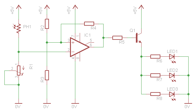
The IC1 (741) along with the resistors R2, R3 and r4 performs the Schmitt Trigger. Instead of a waveform, the input to the 741 comes from a voltage divider, performed by a photocell (PH1) and a potentiometer R1. This potentiometer will eventually set the sensitivity of the circuit.
This is the photocell (LDR) that i use
The output of the Schmitt Trigger is driven through a resistor (R5) to the base of the transistor amplifier. The circuit as-is, may not be able to directly drive a relay with this transistor. If you plan to use this circuit to drive higher loads than LEDs, then you may consider use more amplification stages. I only plan to power some 3-4 LEDs, so the power is enough. Each LED will have its own limiting resistor.
The circuit has a hysteresis that can be adjusted by changing R4. This hysteresis works as follows: The LEDs turn on when a specific amount of light falls on the photocell. The LEDs will remain ON as long as the luminosity is bellow this amount. When the amount of light starts to increase again and goes above this specific point, the LEDs will NOT turn off. Instead, the amount of light must go a little bit higher for the LEDs to turn off. This difference is the hysteresis. The bigger the R4 - the smaller the hysteresis and vice versa.
Any resistor between 100 Ohms and 100 KOhms can be used. But keep in mind that above 40 KOhms, the hysteresis is very small, almost none, so practically there is no meaning to make such a circuit. The point of this circuit is to have this hysteresis. The reason is very simple. Suppose that you use this circuit for security light - the LEDs must turn on when the ambient light is not sufficient. Now suppose that this circuit is outside, and the sun begins to fall. There will be a time, that the amount of light is exactly at the point that the LEDs must turn on. In an ideal world, the LEDs would turn on and remain like this. But this will not happen. Instead, the LEDs will turn on and off every time that the light slightly changes, even for a tiny amount, causing the circuit to oscillate. This is where the hysteresis comes to save the day. When the LEDs turn on, the luminosity will have to change a lot until they turn off again. So, slight light changes will be filtered.
Light falls on the photocell, the LEDs are OFF
My hand drops shadow on the photocell and the LEDs are ON
Bill Of Materials
Resistors
R1
Potentiometer 100 KOhm Linear Rotary 1/2W
R2
Resistor 47 KOhm 1/4 Watt 5% Carbon Film
R3
Resistor 47 KOhm 1/4 Watt 5% Carbon Film
R4
Resistor 22 KOhm 1/4 Watt 5% Carbon Film
R5
Resistor 1 KOhm 1/4 Watt 5% Carbon Film
R6
Resistor 10 Ohm 1/4 Watt 5% Carbon Film
R7
Resistor 10 Ohm 1/4 Watt 5% Carbon Film
R8
Resistor 10 Ohm 1/4 Watt 5% Carbon Film
PH1
LDR 5K-500K Photocell 5x4x2mm 150 mWatt
Transistors
Q1
BC548 Switching and Applications NPN Epitaxial Transistor
Nice design! Curious as to where is all the voltage drop? VIN starts with 5V but Vout is 3.5V. Is this right? If so, any suggestions to reduce the voltage drop?
@arpit You need a completely different circuit. This one will not do. Work on this one:
http://www.pcbheaven.com/circuitpages/Simple_Linear_Fan_Controller/
Then replace the R1 with a set of resistor-LDR. Work out the values.
At 29 March 2014, 12:53:02 user arpit wrote: [reply @ arpit]
Hi,
I need to make a circuit to control the speed of a small dc motor(9v, the type used in toys) on the basis of light intensity. Can I use the output of this circuit to run one such motor. Do I need to make any modifications?
I'm in need of single phase to three phase converter using microcontroller.
I need a help, how to start up with it.
, but i dnt know much about electronics design n those gud stuff, i feel ur the right person to help out my dear friend. Wait for your humble reply.
Hello, I made this circuit and it works just fine. the only problem is the LED brightness is not at its max (50% brightness). what might be the problem? thanks.
@lindiwe there is always difference between simulation and real life. hidden parasitic capacitance and resistance are hidden in the PCB and breadboard tracks...
hello i build the circuit and it works but i have a question. how whats comparison can you make concerning the simuating model and the practical model?? Lastly whats is the outcome you can make on this circuit?? thanks you
At 9 January 2013, 9:31:33 user Fung wrote: [reply @ Fung]
I used this circuit as public lighting, the output drives 3 white LEDs via a BC547 transistor while the value of R4 is 27 kohms. The circuit is still testing and I recorded the time when it lights and turns off (from 17:55 to 7:55 on the next day), the LEDs light when the LDR reaches 82 kohms while below 40 kohms to turn off.
Since the hysteresis is quite huge, so its value is necessary to increase, if a 150 kohms resistor is used, would it produce any problems?
@Greta It can be done with a comparator and an one-shot (monostable) circuit, but as i told yo before this will double the circuit complexity.
The comparator checks the transistor output. When it goes below a certain level (let's say 3 volts) the comparator output goes HIGH. This drives the one-shot circuit which sends only one pulse to your circuit.
Aww, too bad. I have a coil that i momenterely need to send a few volt in reverse direction. The coil works like electro magnet moving a filter. Could it be done with a capacitor that sends short impulse when the power turns off over the coil?
@neer add a 7805 to get 5 volts from the 12 volts (for the circuit). Then replace the LEDs with a relay to get the output for your 12volts load.
At 8 March 2012, 10:44:14 user neer wrote: [reply @ neer]
hey i wanna do this with 12v battery and also output should be 12v for to make my bike's head light automatically on and off what changes should i make in this circuit ??? help pls
@Fung the problem is probably the LDR. Check if the resistance is changed with an ohmmeter. Connect your ldr to an ohmmeter and read the resistance in dark and light.
At 18 June 2011, 5:50:38 user Fung wrote: [reply @ Fung]
I found a problem, the sensitivity of turning off a light (the output) was not high enough, nowhere I tune the 100 kohms variable resistor. For example, when the light is on, I place the LDR to a brighter place, but the light does not turn off. What can I do in order to solve this problem?
hi :) can i ask if which of these can I use as an alternative to the LM741 since im not sure.. since these are only the OpAmp available to the store which we are about to visit to buy components.. and as well as the photocell.. can I use this..?
PHOTOCELL (LDR)
5mm Diameter
this is the only LDR available in the store..
and which of these can i use for this circuit..?
LM324N Low-Power Quad Op Amp (DIL)
LM324N Low-Power Quad Op Amp (SMD)
LM3301N Quad Operational Amplifier (DIL)
LM348N Quad 741 Op Amp (DIL)
LM349N Quad 741 Op Amp High-Speed (DIL)
LM358N Low-Power Dual Op Amp (DIL)
LM3900N Quad Operational Amplifier (DIL)
@Fung yes you can use 324. You can also add the resistor to limit the current. It will be ok.
At 28 April 2011, 15:58:54 user Fung wrote: [reply @ Fung]
Also, do 324 op-amps (LM324 or LM358) applicable in this circuit?
And I think that one more fixed value resistor such as 1 kohm should be connected in series with R1, because the resistance of the LDR can be less than 500 ohms when the light intensity of the surrounding is high.
@Fung yes i am talking about R4, the feedback resistor. Very big or very small values will either have NO hysteresis at all, or the hysteresis will be HUGE and the leds will never turn off.
At 26 April 2011, 14:17:35 user Fung wrote: [reply @ Fung]
This circuit is really good for setting the public lighting system which includes delay lighting feature, i.e. after a certain time of darkness, the lights turn on.
For the sentence "Any resistor between 100 Ohms and 100 KOhms can be used. But keep in mind that above 40 KOhms...", is this point to R4? What problems would occur if the resistance of R4 is larger than 100 kohms or smaller than 100 ohms?

 Home
Home
 Projects
 Experiments
 Circuits
 Theory
 BLOG
BLOG
 PIC Tutorials
 Time for Science


 Contact
 Forum
Forum
 RSS
RSS


 Reddit this

